39 aux cord wiring diagram
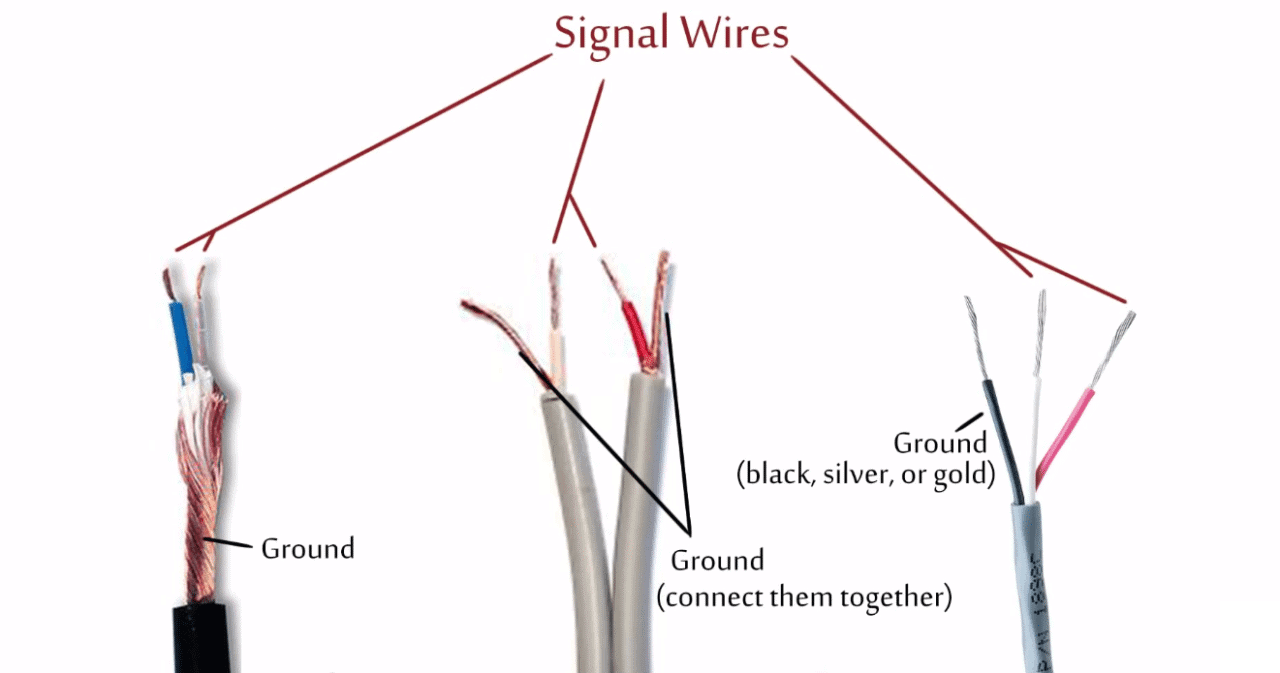
USB wiring diagram- Micro USB pinout, 7+ Images - SM Tech These micro USB C cables are available in different assemblies in different USB versions for various purposes, from USB C charging/ data cable to USB C OTG cable. You can check USB C wiring diagrams and internal wirings of USB 3.0/ 3.1. The image and pinout of USB b super speed are as follows: Audio Cables & Wiring - Sound on Sound A simple helically-wound wire screen (as in the yellow cable) is fine for general-purpose audio cabling, but a braided wire screen (as in the black cable) will tend to give less handling noise with delicate mic signals. Foil or braid screened cables tend to be good from a screening point of view, whereas the type of cable that uses a bunch of ...
1library.co › document › yevgx770-manual-setupMANUAL NO. ZZ26MK SETUP INSTRUCTIONS, LIST OF PARTS, WIRING ... 4 26M-500EKWD Wiring Diagram AR 37 32 AAQPP-03 Plug 2. 5 26M-501K Control Box 1 33 AAQPP-07 Plug 1. 6 26M-502 Plastic Cover 1 34 EP-26MK Eprom 1. 7 26MK-PD Pneumatic Diagram 1 34 35 MM40450010 Latch 1. 8 AAE211E-4 Solenoid Assembly 1 24 36 NNE6-32 Elastic Lock Nut 9. 9 AP-28-610 Aux. Cable 1 37 SSA-0040 Silkscreen AR. 10 EE18-3 Wire 3 38 ...
Aux cord wiring diagram
USB 2.0 cable wiring pinout diagram @ pinoutguide.com The USB 3.0 standard does not directly specify a maximum cable length, requiring only that all cables meet an electrical specification: for copper cabling with AWG 26 wires the maximum practical length is 3 meters. The data cables for USB 1.x and USB 2.x use a twisted pair to reduce noise and crosstalk. USB 3.0 cables are more complex and ... Wiring Diagrams - Home - Winnebago Wiring Diagrams. 2022. 2021. 2020. Electrical Parts Identification List. Wiring Identification Guide. Wiring Diagram Help I have an auxiliary cable which has red , white and black ... Question No auxiliary input on receiver (pioneer vsx-515-k) I have an aux cord that I want to make longer by adding another auxiliary cord but one aux cord has white yellow and red wires: Auxiliary wires color: Hook up a cable that has male yellow and white ends and a single auxiliary mail on the other
Aux cord wiring diagram. en.wikipedia.org › wiki › DIN_connectorDIN connector - Wikipedia Holes on female connectors are also numbered 1-4-2-5-3, but from left to right (facing the holes). The three pins that make contact with a 3 pin DIN connector will have the same pin numbering both in the three-pin and the five-pin connector. A four-conductor cord wired in this way is sometimes called a DIN cord, a DIN lead or a DIN cable. standardscatalog.ul.com › ProductDetailUL Standard | UL 508A 1.15 Portable control panels containing switches, overcurrent protection, and cord connected via attachment plugs and receptacles for use at carnivals, circuses, fairs, exhibition halls, motion picture and television studios, theaters, construction sites and similar locations are covered by the Standard for Portable Power-Distribution Equipment ... Ethernet Cable Color Coding Diagram - The Internet Centre Ethernet Cable Instructions: Pull the cable off the reel to the desired length and cut. If you are pulling cables through holes, its easier to attach the RJ-45 plugs after the cable is pulled. The total length of wire segments between a PC and a hub or between two PC's cannot exceed 100 Meters (328 feet) for 100BASE-TX and 300 Meters for ... › newsletter-sign-upNewsletter Signup - Hollywood.com Newsletter sign up. In subscribing to our newsletter by entering your email address you confirm you are over the age of 18 (or have obtained your parent’s/guardian’s permission to subscribe ...
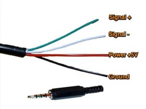
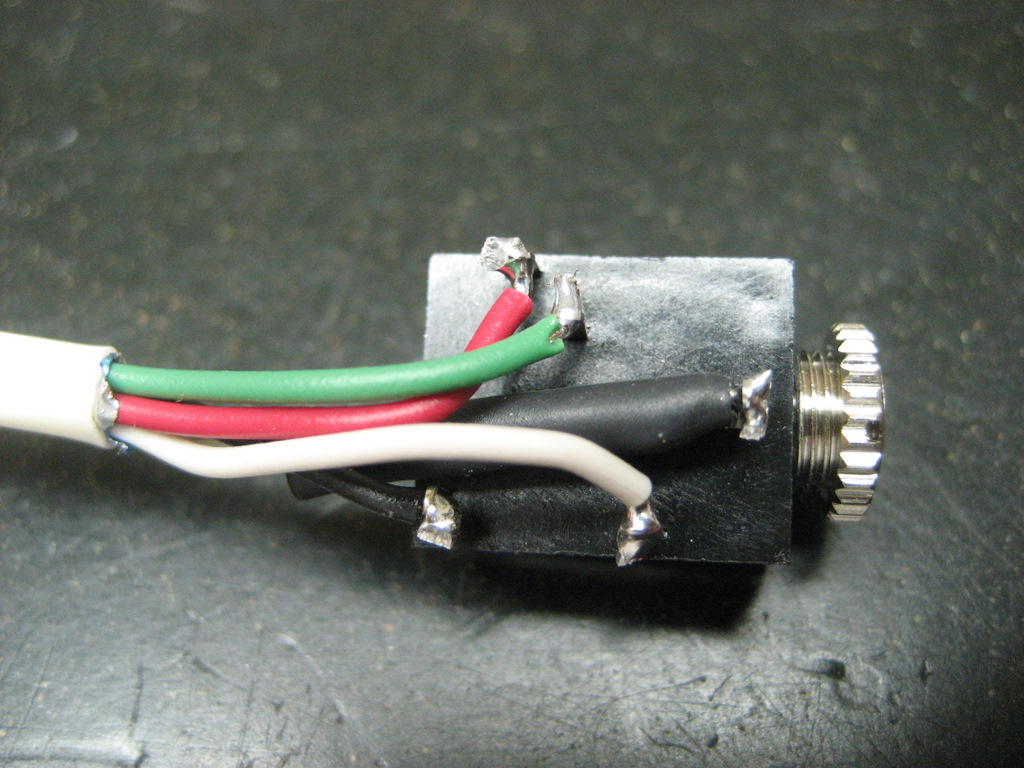
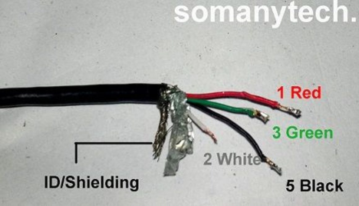
Diy Aux To Usb Cable Wiring Diagram - U Wiring Wiring Diagram Usb To 35 Aux Audio Jack USB Wiring Diagram - May 06 2021 speaker wire usually has 2 insulated wires bonded together so youll need a third for the ground. For any kind of computer to operate properly all the cable televisions must be well linked. Diy hdmi to rca cable wiring diagram. › manual › 1451058WHIRLPOOL CABRIO SERVICE MANUAL Pdf Download | ManualsLib Verify that the red wire coming from the water valve is connected to the ACU, P8-1. This test is performed if the drum LED does Refer to wiring diagrams on pages 25 and 26. not light. Page 24: Strip Circuits FOR SERVICE TECHNICIAN’S USE ONLY STRIP CIRCUITS MOTOR CIRCUIT CENTRIFUGAL DRIVE MOTOR 1/3 HP SWITCH MAIN 3.3-3.6 N.O. RUN CAP . Need Help splicing USB to Headphone cord - Tom's Guide Forum 1)Common (or "ground") (usually connected to bare copper wire) 2)Right (usually connected to red wire) 3)Left (usually green wire) 4)Insulating ring You should be able to hook up the grounds from USB and the 3.5mm. Hook up Left and Right auddio to the +5v and you're good to go. PDF AUX Cable Wiring Diagram - SDR Cube Standard 9-wire serial port DB-9P extension cable DB-9S DB-9S DB-9S DB-9S (Rear view) SDR Cube "AUX" jack on rear panel AUX Cable Wiring Diagram Connects Cube RS-232 serial port to PC/Terminal for bootloading and Terminal Menu access SDR Cube G. Heron / J. Niinikoski Feb 3, 2011
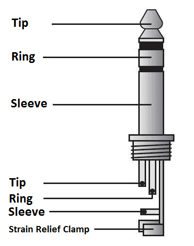
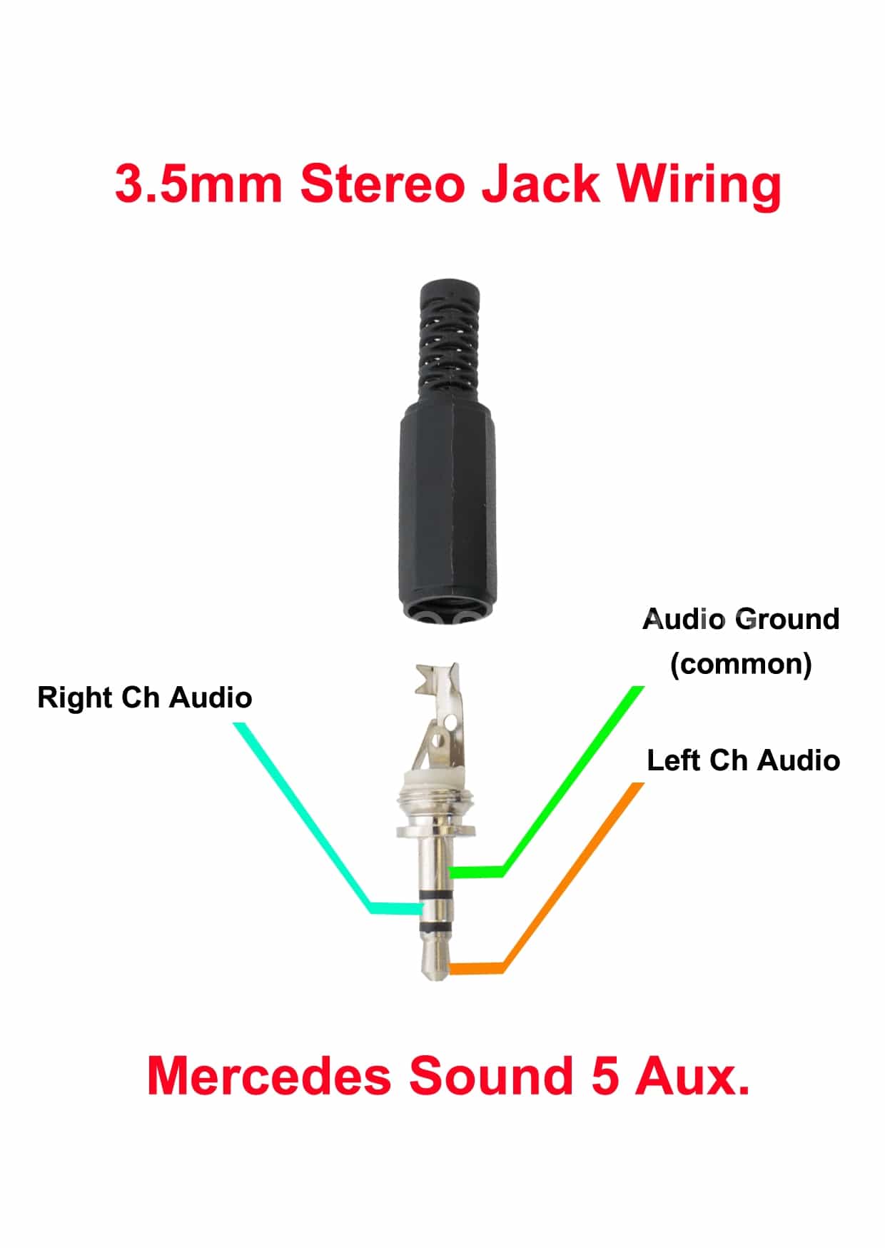
FORD Car Radio Stereo Audio Wiring Diagram Autoradio ... Car stereo wiring diagram radio installation head unit. Car radio wire colors car audio wiring free radio wiring diagrams. Radio diagram wiring car radio car radio wiring diagrams. How to Make a RCA to 3.5mm Cable - Instructables Step 2: Making It. Follow the circuit diagram to make it. If you are using a 3.5 mm audio plug from a pair of headphones then there are four wires coming from it. Two are grounds for each of the RCA plugs and one is the right channel and one is the left channel. Gemeco | Wiring Diagrams - Aux Cord Wiring Diagram ... Auxiliary Cord Wiring Diagram | Manual E-Books - Aux Cord Wiring Diagram. Wiring Diagram contains many comprehensive illustrations that show the connection of various items. It contains guidelines and diagrams for various types of wiring strategies as well as other products like lights, windows, and so on. 3.5mm Stereo Jack Wiring Diagram 3.5mm Stereo Jack Wiring Diagram. 4-Pole Headphone Jack Replacement: Replace a damaged 4-Pole headphone jack (found in Since the wires used in headphones are often very small, this repair is only recommended for individuals with Step 1 4-Pole mm Jack. Wikipedia suggests you're likely going to want to reattach it with the tip hooked to the left ...
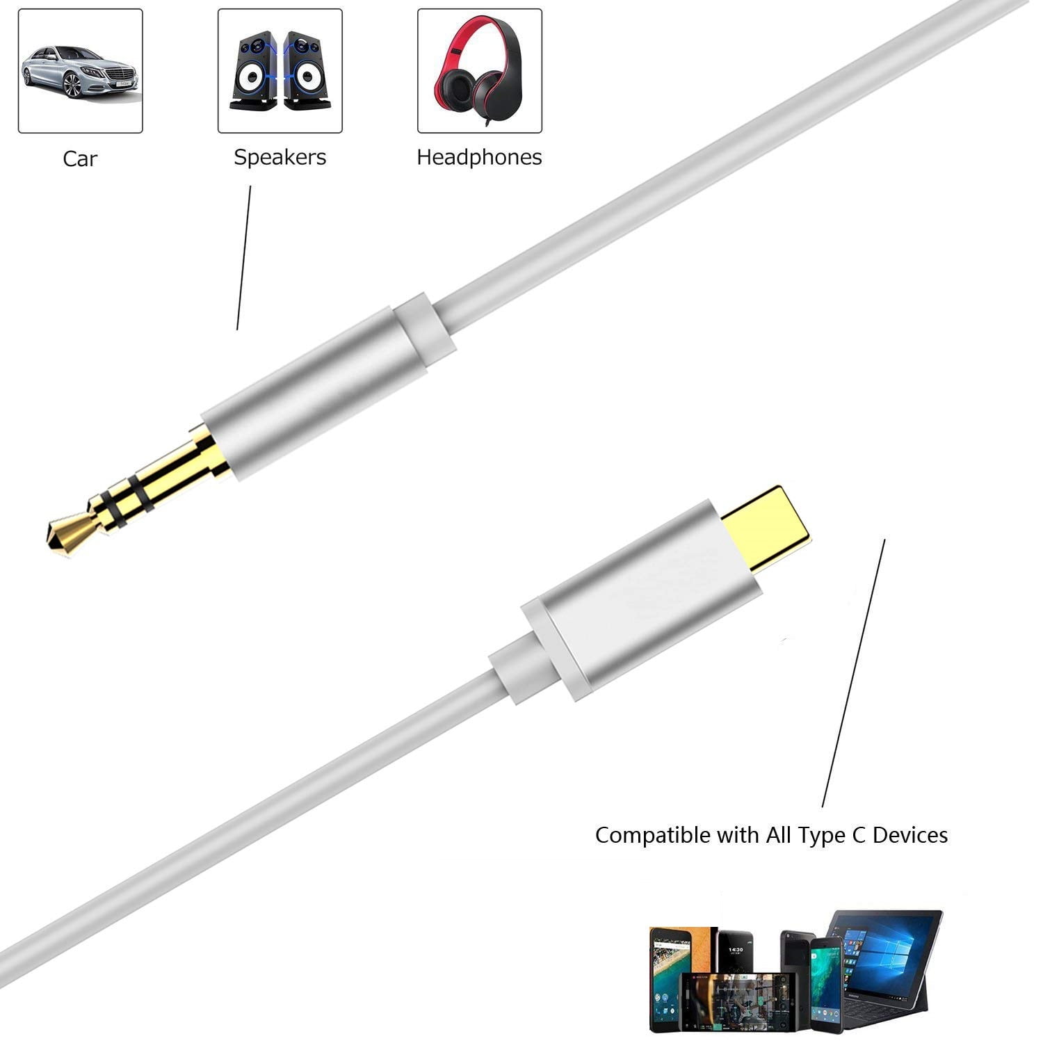
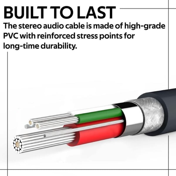
2020 Type C to 3.5 mm Audio Cable for Android, Type C Aux Cable to 3.5mm Audio Aux Headphone Jack Adapter, Audio Stereo Cord Aux Cord for Car, ...
4 Wire Aux Cable Wiring Diagram - U Wiring As stated previous the traces at a Aux Cord Wiring Diagram signifies wires. 3-Series E30 316 83 to 88 316i 88 to 91 318i 83 to 91 320i 87 to 91 325i 87 to 91Also Touring and Convertible versions of these models 5-Series E28 518 81 to 85 518i 85 to 88 525i 81 to 88 528i 81 to 88 535i 85 to 88 M535i 85 to 88 5-Series E34 518i 90 to 91 520i 88 to 91 525i 88.
SOLVED: usb cable to head phone jack .Is it possiable to make ...
Aux Cord Wiring Diagram - Cadician's Blog Gemeco | Wiring Diagrams - Aux Cord Wiring Diagram Wiring Diagram contains many comprehensive illustrations that present the relationship of varied things. It includes guidelines and diagrams for various kinds of wiring strategies along with other products like lights, windows, and so on.
How to Hack a Headphone Jack
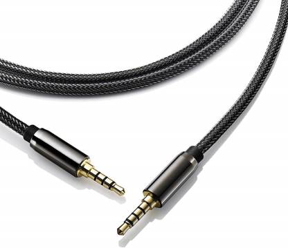
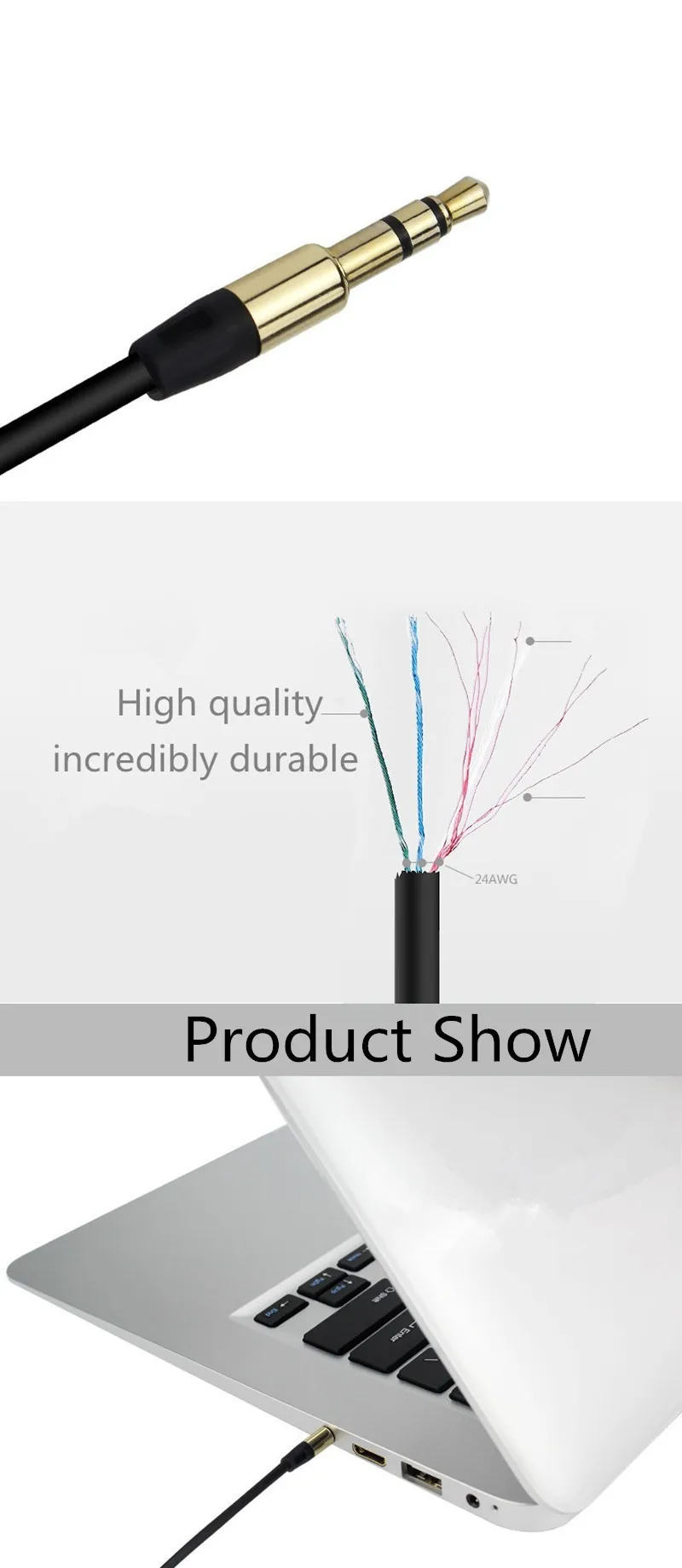
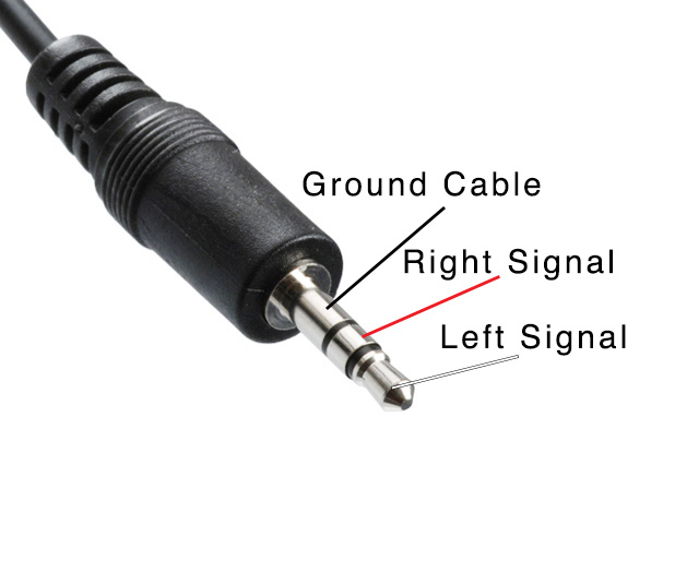
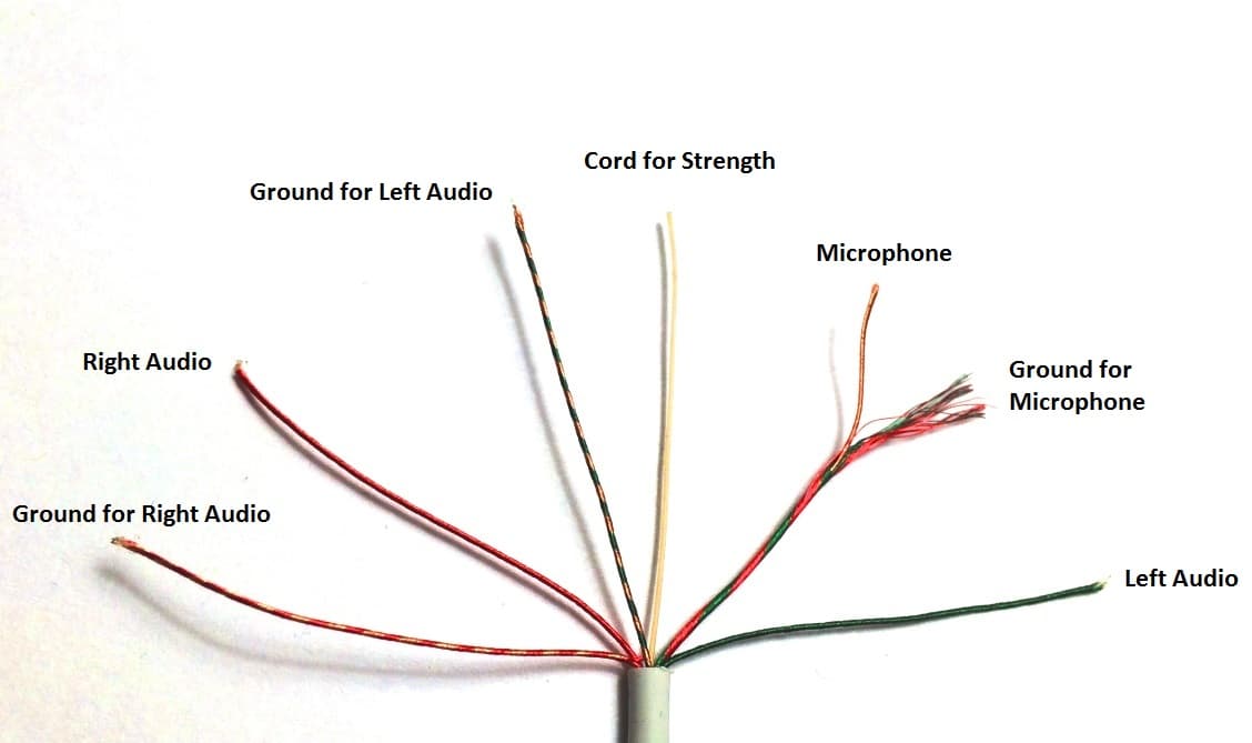
The Ultimate Guide to Audio Connectors and Cables ... A 3.5mm connector is most commonly used for audio on smartphones, portable devices, and computers. The two rings on the connector are for carrying right and left stereo sound. For earphones with a built-in microphone, you'll see the connector has a third ring. This third ring also allows an audio signal to be carried.
What are the terminals of an AUX cable having three wires ...
Complete Wiring Diagrams For Ford Falcon AU, BA, BF, FG ... Complete Wiring Diagrams For Ford Falcon AU, BA, BF, FG - YouTube.

DIY Aux Cable : 6 Steps - Instructables
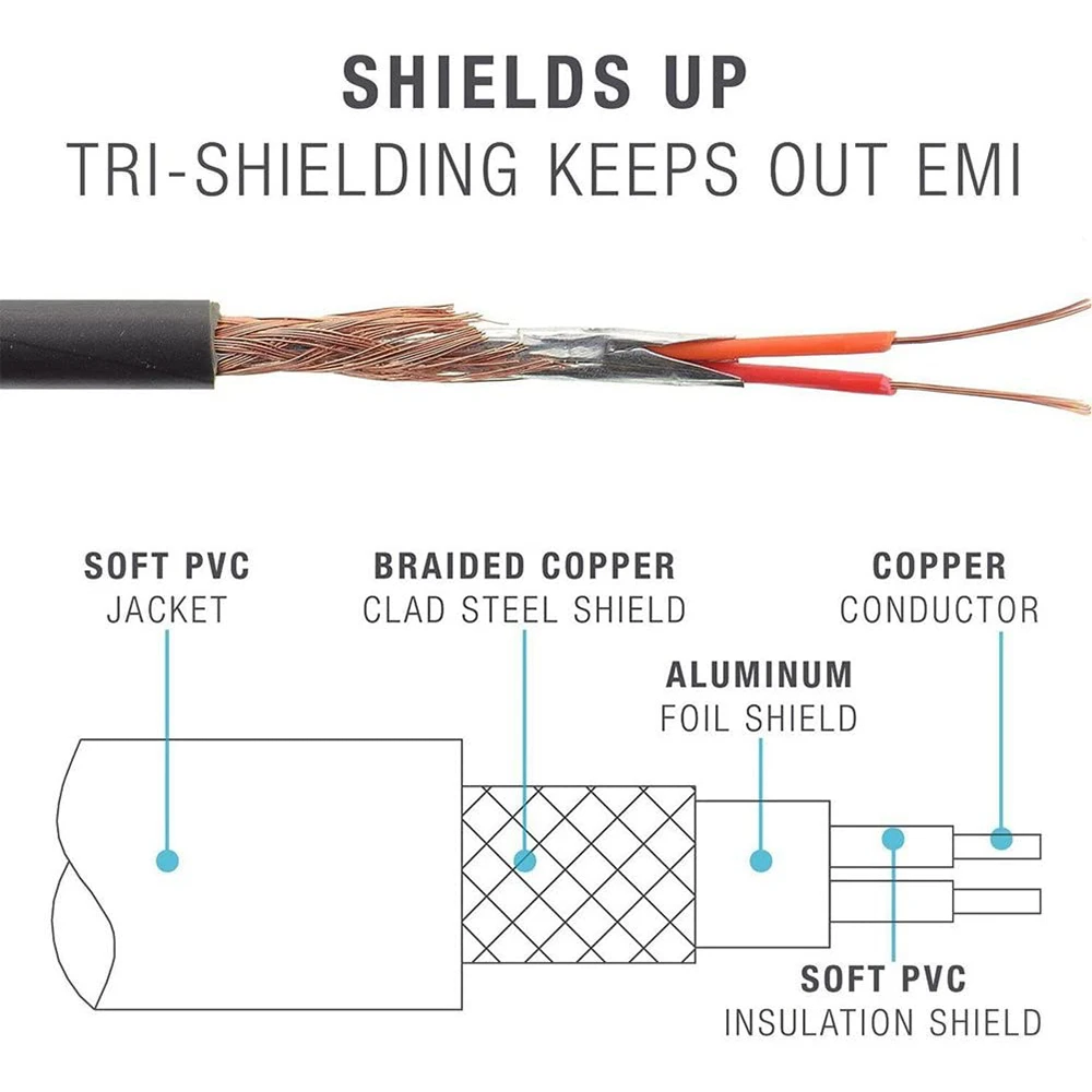
XLR Wiring Standards, Diagram & Pin-out (3 Pin Audio & 5 ... 3 Pin XLR Wiring Standard. 3 Pin XLR connectors are standard amongst line level and mic level audio applications. The above diagram shows you the pin numbering for both Male and Female XLR connectors, from the front and the rear view. (the rear view is the end you solder from) Here are the connections on each pin: Pin 1: Shield / Ground.
مسطرة الحساسية قمة stereo plug wiring - rise-association.com
› manual › 1244310WHIRLPOOL CABRIO WTW8500DC SERVICE MANUAL Pdf Download ... Page 22: Wiring Diagram FOR SERVICE TECHNICIAN’S USE ONLY Wiring Diagram IMPORTANT: Electrostatic discharge may cause damage to machine control electronics. See page 1 for ESD information. NOTE: Schematic shows lock switch open. 120 VAC PUMPS & SHIFTER NOT ON ALL MODELS 3 PHASE SHIFTER RECIRC.
Trailer Wiring Diagram and Installation Help - Towing 101
PDF Wiring Diagram Book - Daltco WIRING CAPACITORS RESISTORS SEMICONDUCTORS Table 1 Standard Elementary Diagram Symbols (cont'd) Iron Core Air Core Auto Iron Core Air Core Current Dual Voltage Thermal Magnetic Single Phase 3-Phase Squirrel Cage 2-Phase, 4-Wire Wound Rotor Armature Shunt Field (show 4 loops) Series Field (show 3 loops) Commutating or Compensating Field (show 2 loops)
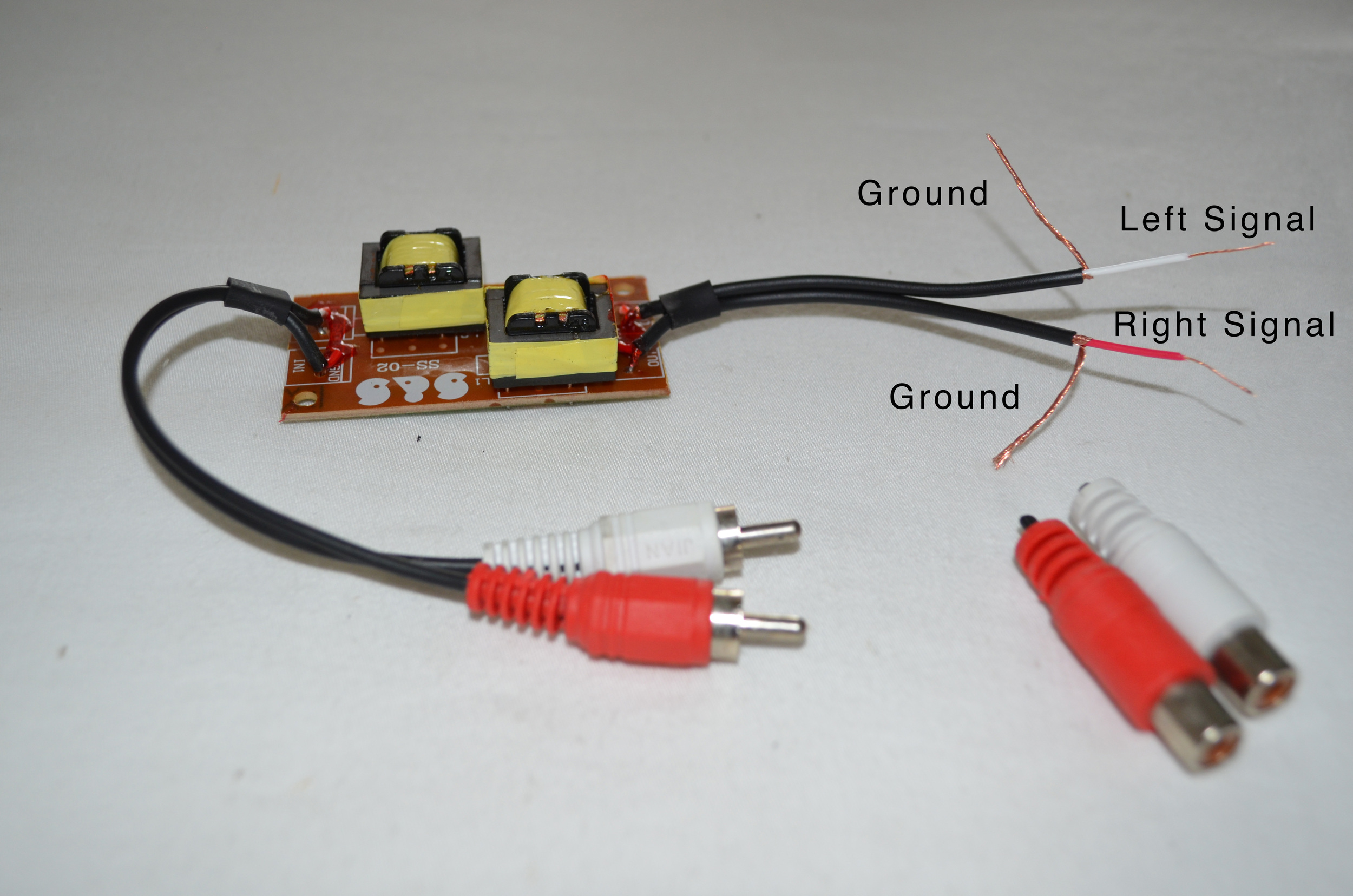
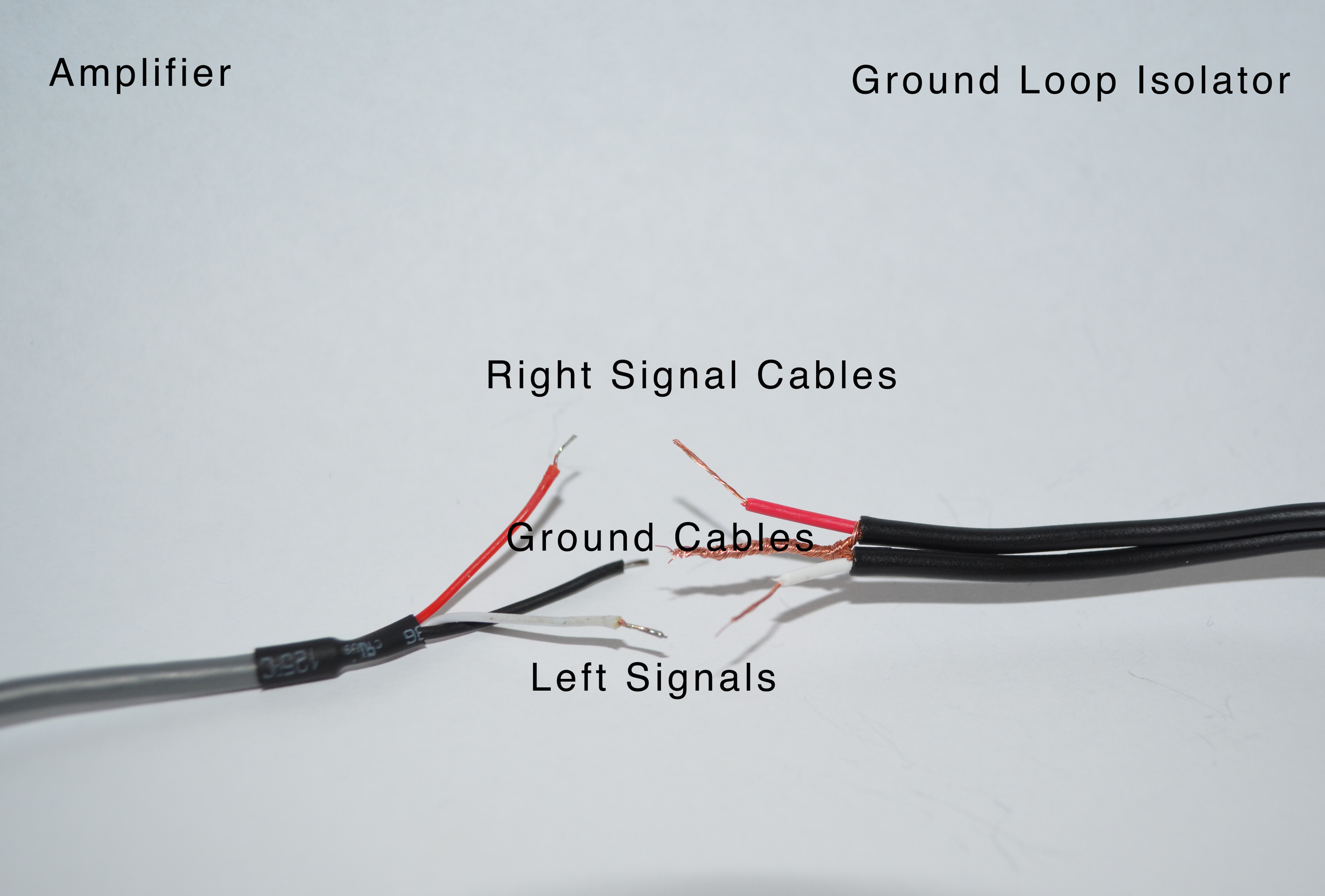
Step 5: Wiring the Audio Signal Cables AMPLFY Speakers AMPLFY
Ford Wiring Diagrams Free Download | Carmanualshub.com Ford Focus Wiring Diagrams PDF.pdf: 6.4Mb: Download: Ford Focus Wiring Diagrams.jpg: 291.8kb: Download: Ford Mustang 1966 Exterior lighting.jpg: 240.2kb: Download: Ford Mustang 2000 Radio Wiring Diagram.png: 214.8kb: Download: Ford Mustang wiring diagram 1968.gif: 184.7kb: Download: Ford 6 (1958 )Wiring Diagrams.jpg: 347.5kb: Download: Ford E-series Electrical Wiring Diagrams PDF.pdf
Voltegic ®4-Pole 3.5mm Male to Male Stereo AUX Extension ...
Aux Cord Wiring Diagram - Wiring Space Aux cord wiring diagram. Each component ought to be set and connected with different parts in. Aux Cord Wiring Diagram aux cord wiring diagram Every electric structure consists of various different parts. Matd s homepage diy install aux in cable for volkswagen installing pure highway 300di dab radio australian ford forums bmw auxiliary audio ...
Corvette Aux Input
PDF Installing Auxiliary Input & iPod Connector First, cut the bus wires we need to use in the MIDDLE. Then use the wiring diagram shown in Figure 3 to wire up your relay. Soldering and heat shrinking (if you can) as shown in Image 3 and 4. Note: a four pole double throw relay was used in this installation; two of the poles were simply not used. Figure 3: Relay Wiring Diagram

How to Make Your Own Aux Cable: 7 Steps (with Pictures) - wikiHow
Aux Cord Wiring Diagram - Wirings Diagram There are two things that will be present in almost any Aux Cord Wiring Diagram. The first element is symbol that indicate electric element from the circuit. A circuit is generally composed by several components. The other thing that you will see a circuit diagram could be traces. Lines in the diagram show how every element connects to one another.

How to Make Your Own Aux Cable: 7 Steps (with Pictures) - wikiHow
Rca Wiring Diagram - Wirings Diagram Lines in the diagram show how each component connects to one another. The positions of circuit components are relative, not accurate. The arrangement is also not logical, unlike wiring schematics. Diagram only reveals where to place component at a spot relative to other components within the circuit.
How to Hack a Headphone Jack
Aux Cord Wiring Diagram - Wiring Diagram Gemeco | Wiring Diagrams - Aux Cord Wiring Diagram Wiring Diagram contains many comprehensive illustrations that present the relationship of varied things. It includes guidelines and diagrams for various kinds of wiring strategies along with other products like lights, windows, and so on.

Buy Replacement Cable Cord for Astro A40/A40TR/A10 Gaming ...
How to Make Your Own Aux Cable: 7 Steps (with ... - wikiHow Speaker wire usually has 2 insulated wires bonded together, so you'll need a third for the ground. Just grab a spare wire from somewhere to use as the third. Connect all the wire to the aux ends, solder, shrink tube it, braid it, then do the same to the other end. I used 18-gauge wire and get excellent signal.

Rankie R-1380 3.5mm to 2-Male RCA Adapter Stereo Audio Cable ...
Wiring Diagrams - DiMarzio Some diagrams may be unavailable during this time. Our apologies for the inconvenience. In the interim, please contact Technical Support: Phone: +1 (718) 816-8112 (Monday through Friday 11:00 AM - 3:00 PM Eastern Time) or email: tech@dimarzio.com. We endeavor to reply to most emails by the next business day.
USB wiring diagram- Micro USB pinout, 7+ Images - SM Tech
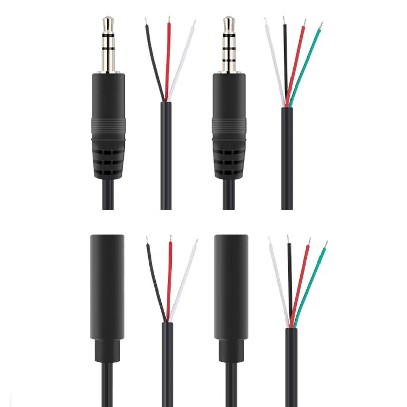
What color wires are in a aux cord? - Mysweetindulgence The white wires allow current passing through the outlet and the other loads on the circuit to return to the panel. What does black dot mean on Aux Cord wiring diagram? Everything rides on circuit that's being assembled. As stated previous, the traces at a Aux Cord Wiring Diagram signifies wires. At times, the wires will cross.

Monster Aux Cord Cassette Adapter 800 - iCarPlay f
TOYOTA Car Radio Stereo Audio Wiring Diagram Autoradio ... connecteur. cable. shema car stereo harness wire speaker pinout connectors power how to install. ( a v.Directos +12) ( 2 +12 v.Accesorios) ( 3 and 11 Left Speaker D) ( 4 and 12 Talking T L) ( 5 and 13 Dercho Speaker D) ( 6 and 16 Talking T Law) ( 7 Light board) ( 8 free) ( 9 +12 v.Ant output.) ( 10 GND).
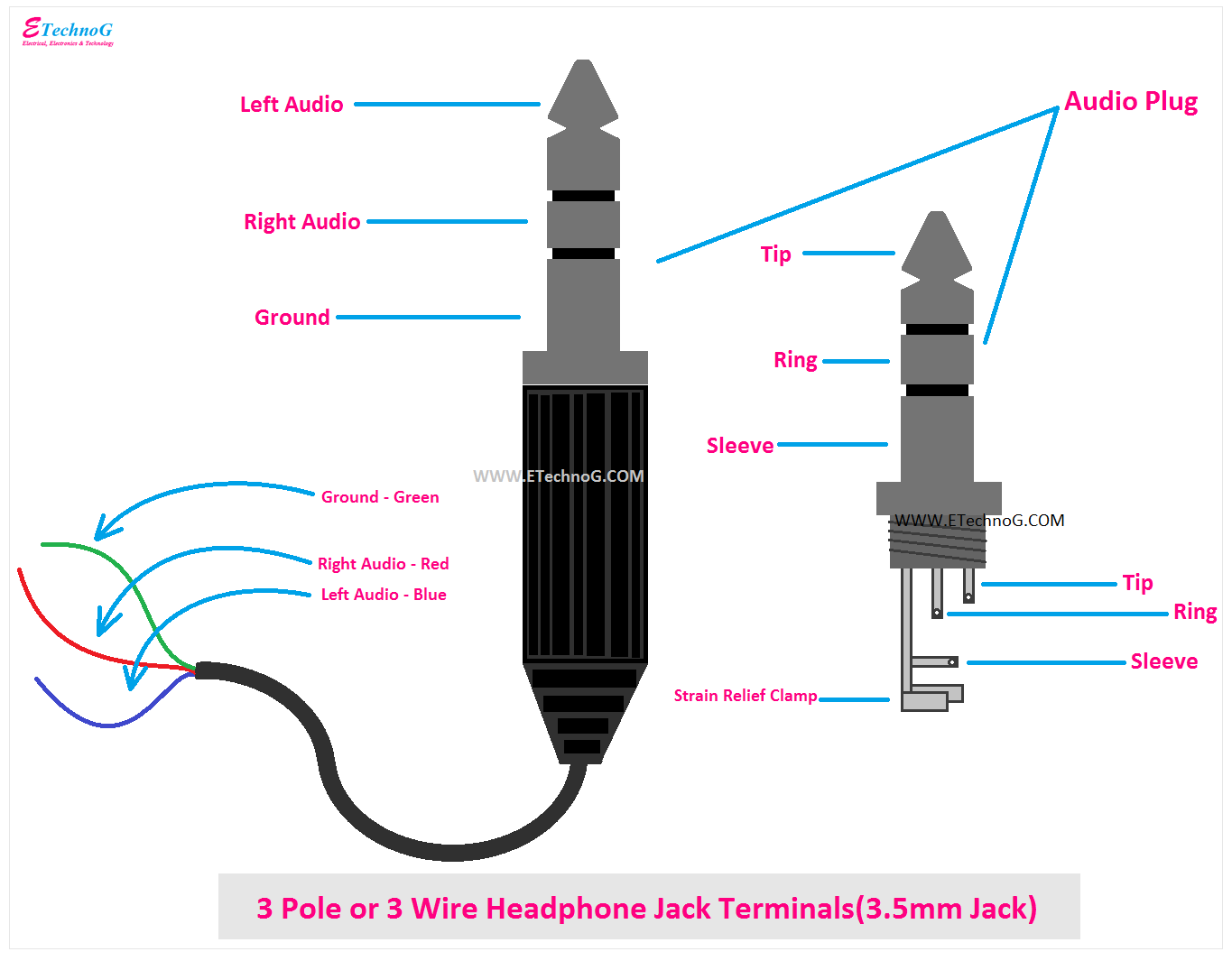
Headphone Jack Wiring, Connection, Terminals, PinOut, Color ...
I have an auxiliary cable which has red , white and black ... Question No auxiliary input on receiver (pioneer vsx-515-k) I have an aux cord that I want to make longer by adding another auxiliary cord but one aux cord has white yellow and red wires: Auxiliary wires color: Hook up a cable that has male yellow and white ends and a single auxiliary mail on the other

3.5 Mm Stereo Jack Wiring Diagram | Electrical wiring diagram ...
Wiring Diagrams - Home - Winnebago Wiring Diagrams. 2022. 2021. 2020. Electrical Parts Identification List. Wiring Identification Guide. Wiring Diagram Help
![iVANKY AUX Cable [Nylon Braided, 8ft, Extra Long] 3.5mm to ...](https://images-na.ssl-images-amazon.com/images/I/71Ex8SBHhdL.jpg)
iVANKY AUX Cable [Nylon Braided, 8ft, Extra Long] 3.5mm to ...
USB 2.0 cable wiring pinout diagram @ pinoutguide.com The USB 3.0 standard does not directly specify a maximum cable length, requiring only that all cables meet an electrical specification: for copper cabling with AWG 26 wires the maximum practical length is 3 meters. The data cables for USB 1.x and USB 2.x use a twisted pair to reduce noise and crosstalk. USB 3.0 cables are more complex and ...
Promate Lightning to 3.5mm AUX Connector 0.15m Black

How Do Headphone Jacks And Plugs Work? (+ Wiring Diagrams ...

Headphone Jack Wiring, Connection, Terminals, PinOut, Color ...
promotional AUX cable wholesale for iphone 7 stereo audio ...
1 x Replacement Aux Extension Audio Cable Cord Wire with In ...

SPCBP Premium 24K Gold Plated Copper Speaker Wire Banana Plug Connecto

Need help in figuring out wires for audio jack replacement ...
Music High Bare Wire Open End De Patch Stackable 3.0mm 3.5mm ...

Buy 2 Pack AUX Cord, Oldboytech Auxiliary Cable [4ft/1.2M, Hi ...

Cable harness Transmission control unit Dodge Cadillac ATS ...
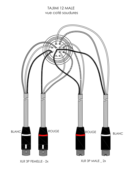
Tajimi 12-pin female output, including internal wiring

How Do Headphone Jacks And Plugs Work? (+ Wiring Diagrams ...

SINDERY Replacement Audio Cable Cord Wire with in-line ...
Step 5: Wiring the Audio Signal Cables AMPLFY Speakers AMPLFY

Aux cable wire connections in detail !!! - YouTube
Step 5: Wiring the Audio Signal Cables AMPLFY Speakers AMPLFY
How to Hack a Headphone Jack

How to Make Your Own Aux Cable: 7 Steps (with Pictures) - wikiHow

China Customized 2 Wire PT100 M5 Brass Threaded Probe Rtd ...
0 Response to "39 aux cord wiring diagram"
Post a Comment