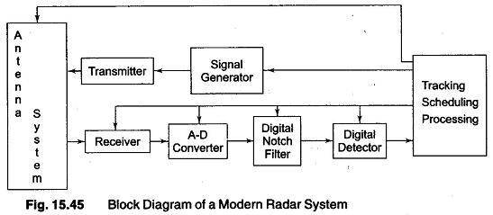
34 radar system block diagram
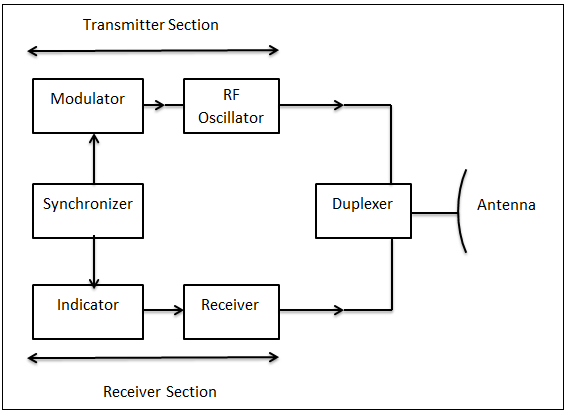
Basic radar block diagram. Synchronizer. The heart of the radar system is the ,synchronizer. It generates all the necessary timing pulses (triggers) that start the transmitter, indicator sweep circuits, and ranging circuits. The synchronizer may be classified as either self-synchronized or externally synchronized. In a self-synchronized system ...
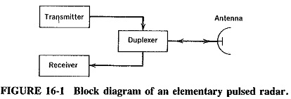
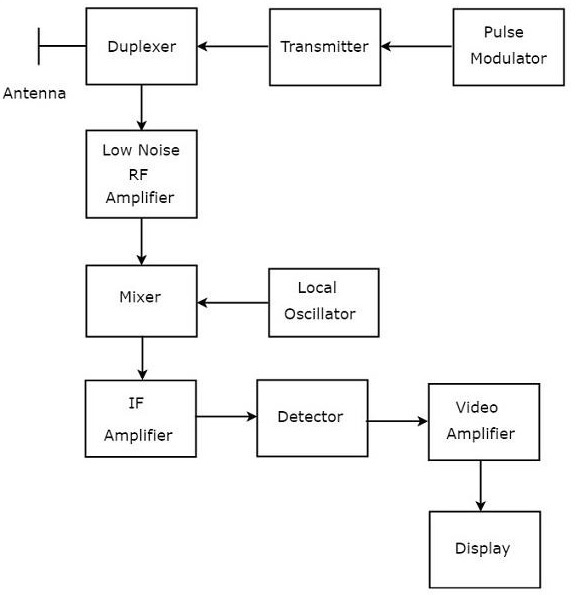
Block Diagram of Pulse Radar Pulse Radar uses single Antenna for both transmitting and receiving of signals with the help of Duplexer. Following is the block diagram of Pulse Radar − Let us now see the function of each block of Pulse Radar − Pulse Modulator − It produces a pulse-modulated signal and it is applied to the Transmitter.
Fig.1 is block diagram of transmitter and receiver of RADAR system using DSSS. Transmitter part consists of binary message signal (Bernoulli Signal), spreading the message signal using PN sequence...
Radar system block diagram
The basic parts of a radar system are illustrated in the simple block diagram of fig.1. Radar equipment consists of a transmitter, an antenna, a receiver, and a signal processor. Radar transmitters...
May 24, 2021 · Basic Radar Block Diagram. A basic radar block diagram is shown in Fig. 1. The pulse repetition frequency is controlled by the timer (also called trigger generator or synchronizer) in the modulator block. The pulse-forming circuits in the modulator are triggered by the timer and generate high-voltage pulses of rectangular shape and short duration.
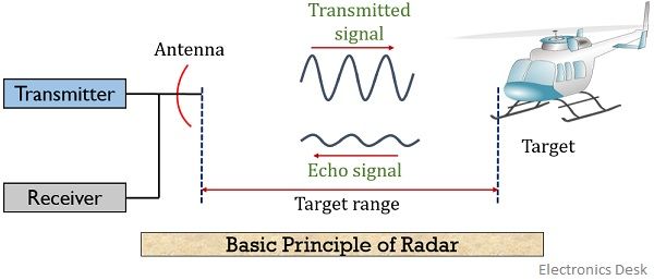
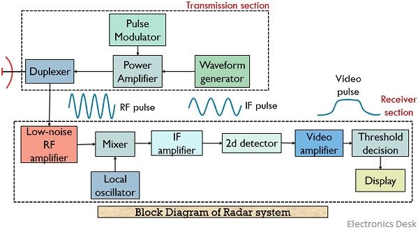
Bistatic Radar System: A bistatic radar system utilizes independent antennas for transmission and reception of the signal. Block Diagram of Radar System. The figure below shows the block diagram representation of radar: We know that a radar system has a transmitting and receiving section. And both the sections perform their respective operation.
Radar system block diagram.
Radar System Modeling. This example shows how to set up a radar system simulation consisting of a transmitter, a channel with a target, and a receiver. For the Aerospace Defense industry, this is an important multi-discipline problem. RF Blockset™ is used for modeling the RF transmitter and receiver sections.
The block diagram in Figure 1 depicts the operation of a generic radar system. Figure 1. Radar Block Diagram [7]. This figure depicts a generic block diagram displaying the interconnectedness of simple radar system. It demonstrates the principles of operation beginning with the ability of a radar to detect ...
Rendezvous Radar System Block Diagram. TRANSPONDER ANTENNA. The transponder utilizes two antenna systems, (Figure Below) a dipole antenna array and two dual spiral antennas. The selected antenna system is connected to the transponder by an antenna select switch. The dipole antenna array is located on an extendable boom which is retracted until ...
Sep 17, 2019 · Block Diagram of Radar: The transmitter can be a power amplifier such as klystron, travelling wave tube etc. It can also be a power oscillator such as magnetron. The radar signal is produced at low power by a waveform generator which is then amplified by the power amplifier. The output of the power amplifier is delivered to the antenna by a ...
SYSTEM INPUT ATTENUATION FOR RSEC MEASUREMENTS B.1 Hardline Coupling to a Radar Transmitter For hardline-coupled measurements, some attenuation will likely be required between the directional coupler output and the measurement device input (see Figure 1). Referring to this diagram, the minimum decibel amount of attenuation, A, required will be:
Block Diagram Of The Radar Sensor Circuit Uses A Branch Line Power Scientific. Block Diagram Of The Realized 24ghz Doppler Radar Sensor I Q Mixer Scientific. Block diagram of the 2 4 ghz doppler radar integrated on printed scientific module sensor circuit uses a branch line power simplified system cw advantages applications limitations realized ...
UWB Radar system block diagram The figure depicts typical block diagram of UWB radar system. RF filter, driver, power amplifier and transmit antenna. The UWB receiver consists of receiving antenna, RF filter (BPF type), LNA (Low Noise Amplifier), down converter(using mixer and LO circuit),
One Chip Radar Detection Circuit Measuring And Test Diagram Seekic Com. Block Diagram Of The Radar Sensor Circuit Uses A Branch Line Power Scientific. One Chip Radar Detection Circuit Under Sensor Circuits 12298 Next Gr. Basic Radar System Block Diagram Fundamentals Frequencies And Powers.
The sub-level block diagram shown in Figure 3 displays the EW digital radar receiver in more detail than Figure 1. Block 1 mixes an analog RF signal with an analog LO frequency from Block 2 to produce an analog intermediate frequency (IF). The IF signal is sampled by Block 3 to be processed by Block 4. In addition, Block 4 controls the LO ...
Simplified Radar Transmitter/Receiver System Block Diagram • Radar transmitter and receiver can be divided into two important subsystems - High power transmitter sections - Low power sections Radar waveform generator and receiver Duplexer Waveform Generator Receiver High Power Amplifier Filter Low Noise Amplifier A/D 00101111010
Block Diagram of Radar System The typical block diagram of radar system is shown in Figure. The essential elements of a radar system are: The timer device is used for coordinating the action of the transmitter, receiver, and indicator, to ensure synchronized operation.
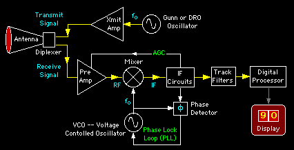
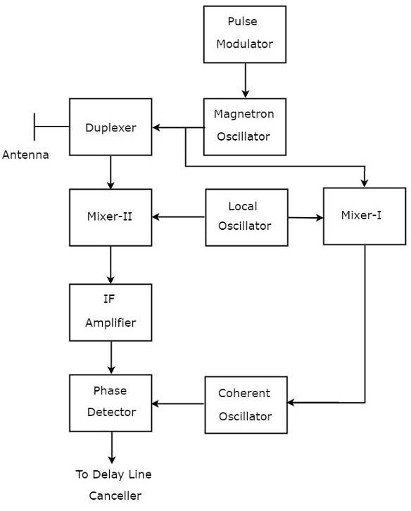
Following figure shows the block diagram of CW Radar − The block diagram of CW Doppler Radar contains a set of blocks and the function of each block is mentioned below. CW Transmitter − It produces an analog signal having a frequency of f o. The output of CW Transmitter is connected to both transmitting Antenna and Mixer-I.
RADAR SYSTEM BLOCK DIAGRAM . Circulator Receiver Protector Synchronous I/ Q Detector ADC and Signal Processor Display Pulse Generator Mixer Mixer Coupler Coupler Oscillator LO PA Radar LNA. ISO 9001 : 2008 Registered Pasternack Enterprises, Inc. P.o. Box 16759, Irvine, CA 92623 Phone: (866) 727-8376 or (949) 261-1920 Fax: (949) 261-7451
MIT IAP 2011 Radar Instructions-1 . GLC 8/28/2012 . MIT Lincoln Laboratory . MIT IAP 2011 Laptop Based Radar: Block Diagram, Schematics, Bill of Material, and Fabrication Instructions* Presented at the 2011 MIT Independent Activities Period (IAP) *This work is sponsored by the Department of the Air Force under Air Force Contract #FA8721-05-C-0002.
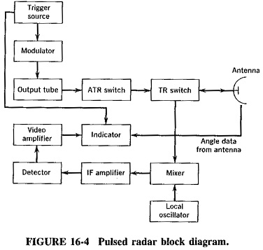
Pulsed Radar System Block Diagram: A very Pulsed Radar System Block Diagram set was shown in Figure 16-1. A more detailed block diagram will now be given, and it will then be possible to compare some of the circuits used with those treated in other contexts and to discuss in detail those circuits peculiar to radar. Block diagram and description:
Radar Modulator Block Diagram. Sreejith Hrishikesan September 27, 2019. • The function of the modulator is to turn on and off the transmitter to generate the desired waveform. When the waveform is a pulse, the modulator is called pulse modulator or pulser. •Energy from the external power source is accumulated in the energy storage element.
Radar Data Processor Figure 1: Universal Block Diagram of Pulse Radar This block diagram may be used for your own lessons but there are no block labels in the animation and there is no background image (landscape). These block labels can be placed in an own layer over the animation in e.g. MS-PowerPoint with text boxes in your own language version.
operation of the radar. The functional block diagram (fig 2) depicts the eight major systems of the TTR which are: synchronizing system, transmitting system, RF (monopulse duplexer) and antenna system, receiver system, ranging system, antenna position system, presentation system, and RF and IF testing system. A
Details about the overall block diagram for the superheterodyne radio receiver: major circuit blocks, functions, overall operation, & electronic circuit design considerations. The superhet radio receiver is used in many forms of radio broadcast reception, two way radio communications and the like. It is useful to have an understanding of the ...
The radar antenna illuminate the target with a microwave signal, which is then reflected and picked up by a receiving device and Radar signals can be displayed on the traditional plan position indicator (PPI) other more advanced radar display systems Fig.2: Block diagram of a primary radar 8.
-- Figure 3-11: Radar System Block Diagram -- Receiver Transmitter The receiver transmitter contains all of the circuitry to gener-ate the RF pulse and to listen for its return. It sends this data to the display in many different ways, depending on the system.-- Figure 3-12:
Figure 2. Block Diagram of Coffee-Can Radar System The block diagram shows the three key parts of this system: the RF electronics (green), audio frequency electronics (blue), and digital signal processing software. The modulator generates the sync-pulse which is used when measuring the range of a target. Note that
System Block Diagram: Figure 2. Block Diagram of Radar System. Figure 2 represents the system's block diagram. Here, it can be seen how the work flow in this radar system. The sensor is going to sense the obstacle and determine the angle of incident and its distance from the radar. The servo motor is constantly rotating to and fro, hence













0 Response to "34 radar system block diagram"
Post a Comment