38 fe si phase diagram
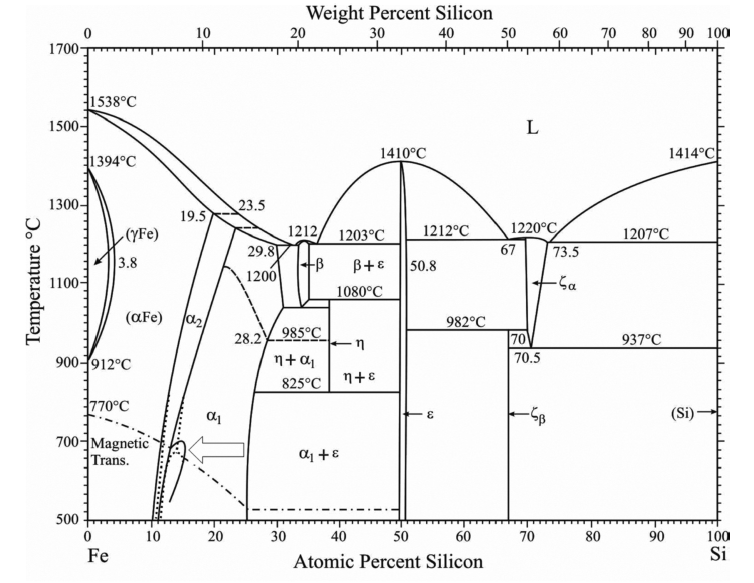
The standard phase diagram for Fe-Si is the one by Kubaschewski (1982). In the iron-rich region, the dominant phases are a-Fe (0 at.%. Si), DO3 (a1, 25 at.%. Si) and B20 (e, 50 at.%. Si). a and a1 have the bcc lattice as underlying lattice, and a1 consists of an ordered replacement of one quarter of the Fe atoms by Si. 307 A. ISAGULOV et al.: DIAGRAM OF EQUILIBRIUM PHASE COMPOSITION OF FE - C - SI - B SYSTEM METALURGIJA 55 (2016) 3, 305-308 It permitted to establish in the Fe - C - Si - B system 7
First, we performed equilibrium calculations for the Fe-Si sys- tem and plotted the equilibrium Fe-Si phase diagram ( Figure 3). We note that B2 BCC is stable up to …
Fe si phase diagram
by I Ohnuma · 2012 · Cited by 69 — develop such practical materials, phase diagrams and ther- modynamic properties of Fe–Si base alloys are helpful and the calculation of phase diagrams ... PHASE RELATIONS OF Mn-Fe-Si-CSYSTEMS Eivind G. Hoel Elkem Mangan KS Sauda, Norway ABSTRACT Phase relations ofMn-Fe-Si-Csystems are established by means ofreported binary diagrams, and calculations of ternary and quaternary diagrams. The phase relations are presented in diagrams for six binary and four higher order deoxidizer, Fe-Mn, Fe-Si, HC Fe-Mn, hot shortness, LC Fe-Mn, MC Fe-Mn, phase diagram, Si-Mn, Ferro-Manganese. Ferro-manganese (Fe-Mn) is a metallic ferro alloy which is added usually along with ferro-silicon (Fe-Si) as ladle addition during steelmaking. It is a ferroalloy composed principally of manganese (Mn) and iron (Fe), and normally ...
Fe si phase diagram. Al-Fe-Mn-Si phase diagram can be used to analyze the effects of Fe and Mn on the phase composition of casting Al-Si alloys of the 4XX.0 series. In many cases, this quaternary diagram solely makes it possible to answer the question as to which Fe-containing phases can be formed in a particular commercial alloy. 1.1. Al-Fe-Si PHASE DIAGRAM Phase Diagram. このサイトを検索. HOME. エリンガム図 / Ellingham diagram. セラミックス / Ceramics. ... Fe-Si. Data from RICT-Sol alloy database ver ... The ternary phase reactions in the system Al-Fe-Si were studied by DTA analysis of samples situated in six different vertical sections at 5 at.%. Al and at constant Fe contents of 27, 35, 40, 50 and 60 at.%. Two heating- and cooling-cycles were performed in each measurement. A set of interdependent thermodynamic values, consistent with the Fe-Si phase diagram, based on a critical assessment of all the published phase diagram and thermodynamic data has recently been submitted by Chart [1]. Simultaneously, Schürmann and Hensgen [2] re-determined the melting and solid state equilibria in the region Fe-FeSi of samples ...
Learn two simple ways to calculate a binary phase diagram in the Fe-C system using the graphical mode of Thermo-Calc. ~~TIMESTAMPS~~0:00 Intro0:42 How to cal... The phase equilibria were studied with Fig. 1 Fe-Ni-Si isothermal section at 850 °C [2009Zha] 184 Journal of Phase Equilibria and Diffusion Vol. 31 No. 2 2010 Phase Diagram Evaluations: Section II optical and scanning electron metallography, x-ray powder References diffraction, and energy dispersive x-ray analysis/electron probe microanalysis. Abstract. In this work Thermo-Calc software was used to calculate the phase diagram of the Fe-Si system. The deduced phase diagram includes twenty fields, where three fields represent pure phases; two solid solutions and a liquid phase. There are several fields of two co-existing phases; mixed solid phases, and mixed solid with liquid phases. Computer calculations of metastable and stable Fe-C-Si phase diagrams from binary thermodynamic properties Computer calculations of metastable and stable Fe-C-Si phase diagrams from binary thermodynamic properties. Files. r_8627100.pdf (1004.34 KB) Date. 1986. Authors. Chueh, Shan-Chang. Journal Title. Journal ISSN. Volume Title. Publisher.
Section-Editor: Hiroaki Okamoto (Phase Diagrams) Cite this content Pierre Villars (Chief Editor), PAULING FILE in: Inorganic Solid Phases, SpringerMaterials (online database), Springer, Heidelberg (ed.) SpringerMaterials Fe-Si Binary Phase Diagram 0-5 at.% TDmeph IRSN Mephista nuclear database (0) TDnucl IRSN Nuclea nuclear database (0) SpMCBN Spencer Group M-C-N-B-Si alloys (837) subsolidus phase diagram of FeSi are directly relevant to the CMB region. Second, the high‐pressure phase diagram of FeSi will help to constrain the topology of the Fe‐rich portion of the Fe‐Si system, which is important in deter-mining the distribution of Si within the core and lower mantle at the present day and during core formation Fe-Si-Y Isothermal Section of Ternary Phase Diagram ... Phase diagram available to subscribers; If you are having trouble in accessing SpringerMaterials remotely during the COVID-19 pandemic, Get help with remote access; To view content, please Log in, ...
The Fe-Si phase diagram: from electrical steel to the planet ...
Second, the high-pressure phase diagram of FeSi will help to constrain the topology of the Fe-rich portion of the Fe-Si system, which is important in determining the distribution of Si within the core and lower mantle at the present day and during core formation [Dobson et al., 2002; Santamaría-Pérez and Boehler, 2008].
Phase Diagrams Evaluation
2.1. Al-Mg-Si PHASE DIAGRAM The Al-Mg-Si phase diagram can be used for the analysis of many wrought alloys of 6XXX series and casting alloys of the 356.0 type, provided the concentration of iron impurity is low (Table 2.1). This diagram is also the basic diagram for casting alloys of the 512.0 type that are considered in Chapter 4.

SciELO - Brasil - Experimental and computer thermodynamics ...
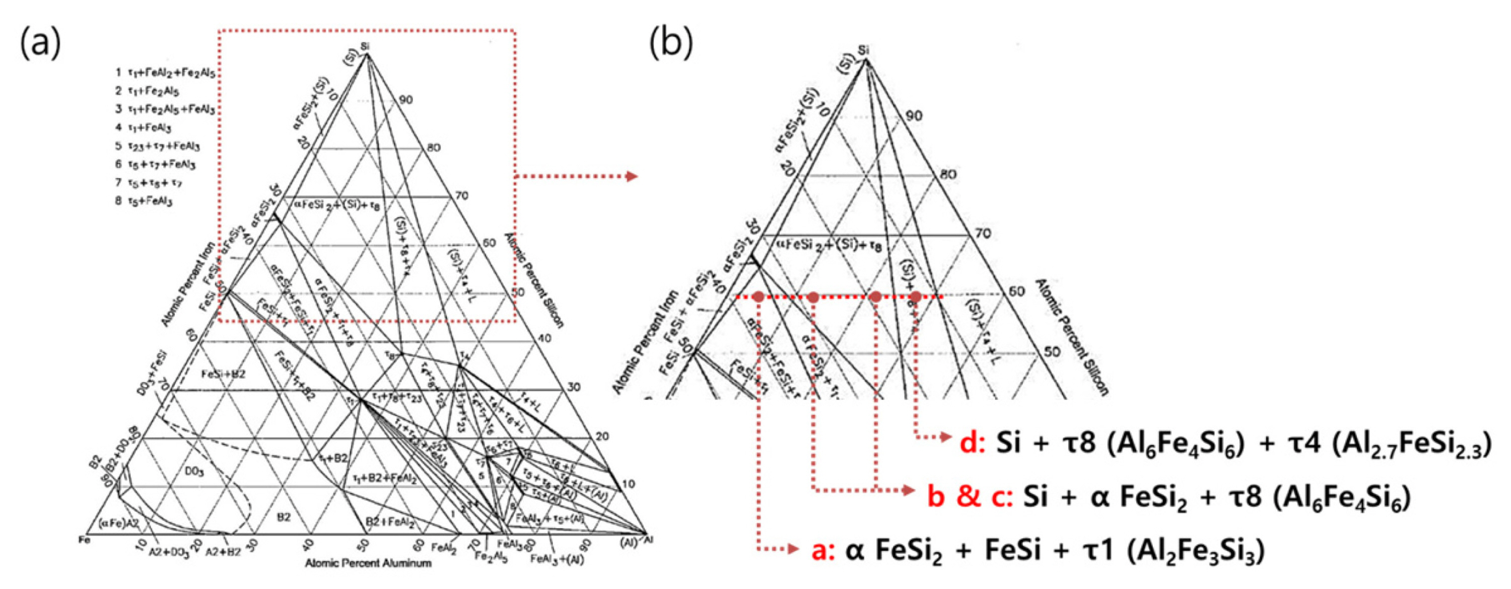
Phase diagram Al-Fe-Si Abstract This document is part of Subvolume A ‘Nonequilibrium Phase Diagrams of Ternary Amorphous Alloys’ of Volume 37 ‘Phase Diagrams and Physical Properties of Nonequilibrium Alloys’ of Landolt-Börnstein - Group III Condensed Matter.
![Fe-Si Phase Diagram [16] and alloy quench temperatures ...](https://www.researchgate.net/profile/Shaghayegh-sherry-Esfahani/publication/257786929/figure/fig1/AS:328356257124352@1455297640212/Fe-Si-Phase-Diagram-16-and-alloy-quench-temperatures.png)
Fe-Si Phase Diagram [16] and alloy quench temperatures ...
by E Edmund · 2022 — To this end, the crystal structures of Fe–Si alloys spanning the entire Fe–FeSi phase diagram have been studied in situ at high P-T conditions ...
Example E1: Stable and meta-stable phase diagram of Fe-C-Mn ...
Fe 2 Si (monoclinic crystal structure) will form. The Al-Si Phase Diagram The binary Al-Si phase diagram was initially studied by Fraenkel of Germany in 1908. It is a relatively simple binary ...
Cu-Fe-Si (Copper-Iron-Silicon) | SpringerLink
Phase Diagram Resources from ASM International. Alloy phase diagrams and crystal structure data are used by metallurgists, materials engineers, and materials scientists to develop new alloys for specific applications; fabricate these alloys into useful configurations; design and control heat treatment procedures for alloys that will produce the required mechanical, physical, and chemical ...
Chapter 8 Phase Diagrams
Fe-Si phase diagram ( Fig. 2(a)) there are two eutectic points: (1) at 1 195°C and 19 wt% Si and (2) at 1 202°C and 21.5 wt% Si; there are also two eutectic points for the Mn-Si phase diagram ...
Thermodynamic assessment of the Al-Fe-Si system
Section-Editor: Hiroaki Okamoto (Phase Diagrams) Cite this content Pierre Villars (Chief Editor), PAULING FILE in: Inorganic Solid Phases, SpringerMaterials (online database), Springer, Heidelberg (ed.) SpringerMaterials Fe-Si Binary Phase Diagram 0-100 at.%
To fax number: +86 592 602 3466
58 function of composition. Some work has previously been done on high P-T phase diagrams of 59 iron-silicon alloys. Fischer et al. (2012) studied the subsolidus phase relations and melting curve of 60 Fe-16wt%Si alloy (Fe-16Si) to 140 GPa (Figure 1). Asanuma et al. (2008) investigated Fe-3.4Si,

Thermodynamic evaluation of Sr-containing Si metals and ...
A systematic characterization of a less known Al, Fe, Mn, and Si phase in a SiC particulate-reinforced 2014Al composite (SiC p /2014Al) was performed. In addition to the expected CuAl 2 phase, the Al, Fe, Mn, and Si phase was formed as either an adhesion (>1 µ m) onto SiC in the as-cast composite, or as a precipitate (<100 nm) in the matrix after hot extrusion.
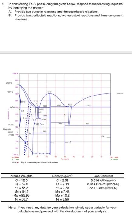
Solved 5. In considering Fe-Si phase diagram given below ...
analysis, a small amount of the Fe-Si-Al flakes with a nearly equal mass of 0.071 g was weighed to exclude change in the demagnetization field with the changing mass and then
Teach Yourself Phase Diagrams and Phase Transformations
Si Mn W Mo Review Fe-C phase diagram • 2 important points-Eutectoid (B): γ⇒α+Fe 3C-Eutectic (A): L ⇒γ+Fe 3C Fe 3 C (cementite) 1600 1400 1200 1000 800 600 400 0 12 3 4 5 66.7 L γ (austenite) γ+L γ+Fe 3C α+Fe 3C α + γ L+Fe 3C δ (Fe) C o, wt% C 1148°C T(°C) α 727°C = Teutectoid A R S 4.30 Result: Pearlite = alternating layers ...
Sigma-phase in Fe-Cr and Fe-V alloy systems and its physical ...
The composition of the τ 5 phase can be approximately represented by the formulae Fe 2 Al 7 Si, which is close to the (Fe 17 Al 72 Si 11) phase reported by Murav'eva et al. . The K 5 phase of Takeda and Mutuzaki [1] , which is supposed to be the same phase as τ 5 , is reported to have a different composition, Fe 6 Al 15 Si 5 .
The Al-Rich Part of the Fe-Al Phase Diagram
The Al-Si Phase Diagram The binary Al-Si phase diagram was initially studied by Fraenkel of Germany in 1908. It is a relatively simple binary diagram where there is very little solubility at room temperature for Si in Al and for Al in Si. Thus, the terminal solid solutions are nearly pure Al and Si under equilibrium conditions.
Influence of Cu on modifying the beta phase and enhancing the ...
1. Phase diagram of pure iron 9 2. Phase diagram of the Fe-Si system at 1 bar 11 3. Phase diagrams of Fe-Si alloy containing 8 wt.% Si from Lin et al.(2002) 13 4. Phase diagram of Fe-Si alloy containing 8 wt.% Si from Lin et al.(2009) 15 5. Phase diagram of FeSi3.4 16 6. Solubility of silicon in FCC iron 17 7.
PHASE RELATIONS OF Mn-Fe-Si-C SYSTEMS
Ternary phase diagram books by D.R.F. West - there are several . Ternary grid . Space diagram . C A B . Space diagram . Usually have elements at the corners as the constituents, ... For diagrams where there is a major . component, e.g. Fe in Fe-C-Cr, use a . right-angled triangle → ...

Characterization of the evaluation of the solid solubility of ...
FIG. 1. Schematic temperature-composition (T-X) phase diagram (black dashed lines) of iron-rich Fe-Si alloys at about 16+2 GPa. Crosses indicate bcc+hcp; open circles indicate hcp only; open squares indicatefcc+hcp; X’s indicate fcc only; solid squares indicatebcc+fcc+hcp; open triangles indicatebcc+fcc; and tie lines indicate

Geos 306, Lecture 13, Mineralogy of the Earth and its Core
deoxidizer, Fe-Mn, Fe-Si, HC Fe-Mn, hot shortness, LC Fe-Mn, MC Fe-Mn, phase diagram, Si-Mn, Ferro-Manganese. Ferro-manganese (Fe-Mn) is a metallic ferro alloy which is added usually along with ferro-silicon (Fe-Si) as ladle addition during steelmaking. It is a ferroalloy composed principally of manganese (Mn) and iron (Fe), and normally ...

Computer calculations of metastable and stable Fe- C-Si phase ...
PHASE RELATIONS OF Mn-Fe-Si-CSYSTEMS Eivind G. Hoel Elkem Mangan KS Sauda, Norway ABSTRACT Phase relations ofMn-Fe-Si-Csystems are established by means ofreported binary diagrams, and calculations of ternary and quaternary diagrams. The phase relations are presented in diagrams for six binary and four higher order
![PDF] Assessment of the ternary Fe–Si–B phase diagram ...](https://d3i71xaburhd42.cloudfront.net/6d7e78e3f8f05fa511ab11788407d75a18da9b0b/14-Figure3-1.png)
PDF] Assessment of the ternary Fe–Si–B phase diagram ...
by I Ohnuma · 2012 · Cited by 69 — develop such practical materials, phase diagrams and ther- modynamic properties of Fe–Si base alloys are helpful and the calculation of phase diagrams ...
The dependence of the ß-AlFeSi to α-Al(FeMn)Si transformation ...

PDF) Fe-Ni-Si (Iron-Nickel-Silicon) | Vijayaraghavan ...
Perple_X vs THERMOCALC and/or Thermo-Calc
Thermodynamic and kinetic analysis of the melt spinning ...
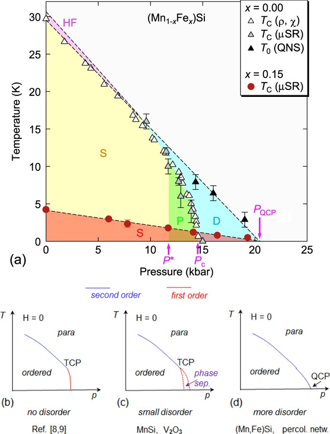
Restoration of quantum critical behavior by disorder in ...
The iron-iron carbide (Fe-Fe3C) phase diagram Microstructures ...
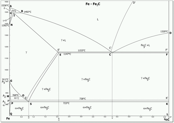
Iron-carbon phase diagram
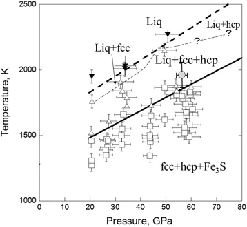
Melting relations in the Fe–S–Si system at high pressure and ...

The FeSi phase diagram to 150 GPa - Lord - 2010 - Journal of ...
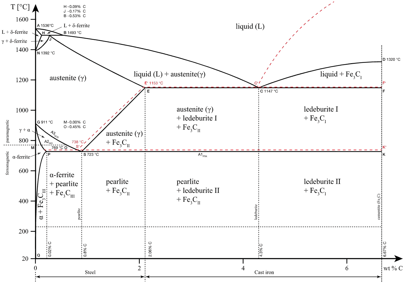
Iron-Carbon Alloys | nuclear-power.com
Thermo-Calc of the Phase Diagram of the Fe–Si System ...
Investigation on the 773 K isothermal section of Dy–Ni–Si ...
The dependence of the ß-AlFeSi to α-Al(FeMn)Si transformation ...
Thermodynamic modeling of Al–Fe–V ternary system
Fundamental Approach to Capacity Prediction of Si-Alloys as ...
MSI - Material Science International - Phase Diagrams
The Fe-FeSi phase diagram at Mercury's core conditions ...

Crystal structure and equation of state of Fe-Si alloys at ...
0 Response to "38 fe si phase diagram"
Post a Comment