40 brushless motor winding diagram
Electrical Circuit Diagram ... Electrical Winding - EE Figures: Electrical Winding ... Muita gente tem-me perguntado como enrolar um motor Brushless, ... Brushless Dc Motor Winding Diagram Home Electrical Wiring, Electrical Circuit Diagram, Electrical Projects,. Visit. Save. From. br.images.search.yahoo.com ...
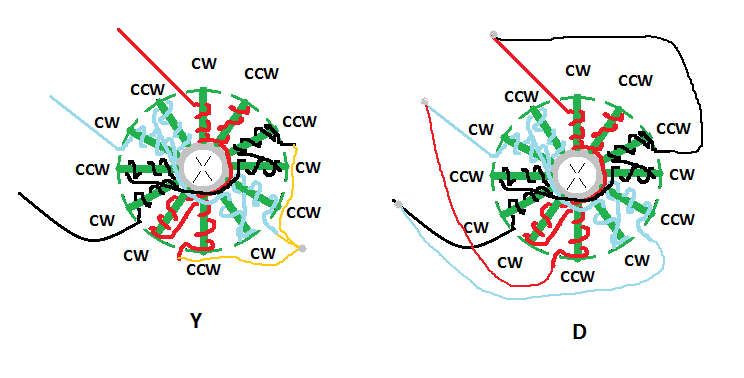
DELTA vs WYE (STAR) Termination. Theoretically, the ratio between Delta and Wye is 1.732 (square root of 3). However, in practise this number is closer to 1.8. Therefore, a motor with a given number of turns, terminated WYE, would yield ~1.8 times more Kt (torque per amp) than a similarly wound motor that is terminated Delta, while the Kv (RPM/volt) would be ~1.8 times lower.
Brushless motor winding diagram
Brushless Dc Motor Winding Diagram Home Electrical Wiring, ... Muita gente tem-me perguntado como enrolar um motor Brushless, então resolvi postar aqui a ... Brushless DC Motors K. Craig 5 • Windings - Consider the diagram of the elementary two-pole, single-phase stator winding. - Winding as is assumed distributed in slots over the inner circumference of the stator, which is more characteristic of the stator winding than is a concentrated winding. Brushless Dc Motor Winding Diagram Home Electrical Wiring, ... Muita gente tem-me perguntado como enrolar um motor Brushless, então resolvi postar aqui a ...
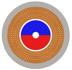
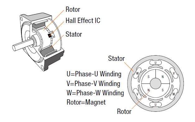
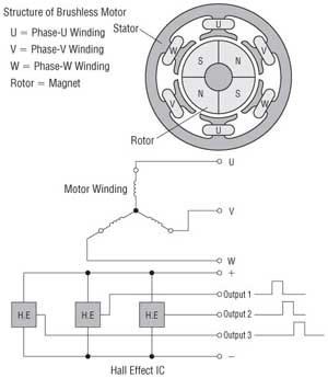
Brushless motor winding diagram. Brushless Dc Motor Winding Diagram Home Electrical Wiring, ... Muita gente tem-me perguntado como enrolar um motor Brushless, então resolvi postar aqui a ... The stator is made of thin metal sheets and several windings of copper wire form electromagnets that can create magnetic fields that can be controlled by your ESC. For three phase brushless motors, the number of stator poles is always a multiple of three. In the case of the BR1103B you can count nine stator shoes. The number of magnets in the ... Electric motor winding calculator. The winding calculator allows you to find the optimum winding layout for your electric motor in a fast and convenient way. You can investigate three-phase integer-slot, fractional-slot and concentrated windings, both with single and double winding layers where appropriate. Figure 1-1 shows the functional block diagram of the 3-phase BLDC motor operation. A BLDC motor has a rotor with permanent magnets and the stator contains the windings. 3 Phase Brushless Dc Motor 3 Phase Brushless Dc Motor Controller Brushless Esc Brushless Motors 3phase Inverters Sc Control Motor Electronics Circuit Construction of BLDC Motor. Bldc […]
User Guide Gbxâ Brushless Motor Calculator Gobrushless Com. Handbook Of Electric Machines. Design Optimization And Analysis Of An Outer Rotor Direct Drive Permanent Magnet Motor For Medium Sd Electric Vehicle. No 13 winding diagram for an ac motor simulation technology electromechanical design jmag 45kw bushless motor design brushless motors ... Brushless Motor Disassembly and Rewinding.Turnigy 5208 rewinding 150 turns to 210 turns.Poles: 12N14PTermination: starThe wiring diagram and step by step in... Brushless DC Motor Drives, Speed Control and Electrics | ResearchGate, ... Most BLDC motors have three phase stator windings, while their rotors can have ... A very important part of winding a brushless motor is making certain that you can pack in the most amount of copper as possible. Doing so will increase the efficiency of the motor. These smaller diameter strands of wire will allow the windings to be packed very tight decreasing the amount of voids in the windings. Take a look at this motor below.
stator has the same number of windings. Out of these, 3-phase motors are the most popular and widely used. This application note focuses on 3-phase motors. Stator The stator of a BLDC motor consists of stacked steel laminations with windings placed in the slots that are axially cut along the inner periphery (as shown in Figure 3). A BLDC motor overcomes the requirement for a mechanical commutator by reversing the motor set-up; the windings become the stator and the permanent magnets become part of the rotor. The stator is typically comprised of steel laminations, slotted axially to accommodate an even number of windings along its inner periphery. You are looking for a big Brushless DC Motor for your Electric Car or Powered Paraglider? I show you how to make the winding. The Rotor and Stator parts I ha... Nov 20, 2018 - This Pin was discovered by Anas Aswadi. Discover (and save!) your own Pins on Pinterest.
A brushless motor is constructed with a per- ... the wound stator poles. FIGURE 1: SIMPLIFIED BLDC MOTOR DIAGRAMS Author: Ward Brown Microchip Technology Inc. N S A C a a b b c c B com com com N N S S 110 010 011 101 100 001 N S S N 6 3 4 1 2 5 A C B c b a com Brushless DC Motor Control Made Easy. ... mutate the winding currents is by means of ...

14+ Brushless Dc Motor Controller Circuit Diagram. Brushless dc motor drive as described above that the electronic controller circuit energizes appropriate motor winding by turning transistor or other solid state switches to rotate the motor continuously. In the circuit there are 2 pushbuttons, one is used to increase bldc motor…

You will need: brushless motor with a 12 tooth stator and 14 magnets 200-400 grit sandpaper Enamel coated wire Wire cutters Pliers I used a hexTronik DT or D40xx motor, They are great for this experiment because they are large, easy to rebuild, and can hold a wide range of wiring configurations that can handle around 150-650W and 400-2000kv. They work best on 2-4 cell lipo batteries with a 7 ...

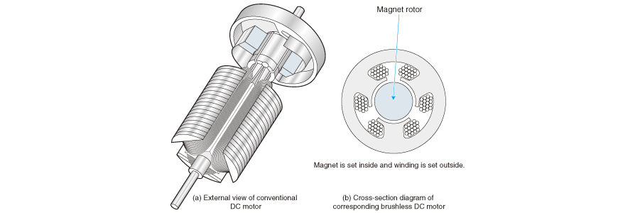
Constructional Features of Brushless dc motor. Fig. 1 illustrates this type of motor with the help of a simple block diagram. In conventional d.c motor, field magnets are placed on the stator and armature winding is placed on the rotor. However, brushless dc motor has a polyphase winding (armature) on the stator and permanent magnets on the rotor.

Dc Motor Winding Diagram Pdf. Construction of dc motor your brushless dc motors bldc what are construction of dc motor electrical electric motor design basic tutorial. Permanent Magnet Dc Motor Its Applications Advantages Disadvantages Circuit Globe. Schematic Of 36 Slot 4 Pole Stator Winding Generated With The Bobisoft Scientific Diagram.

Keeping that in mind, a BLDC Motor is a type of synchronous motor in the sense that the magnetic field generated by the stator and the rotor revolve at the same frequency. Brushless Motors are available in three configurations: single phase, two phase and three phase. Out of these, the three phase BLDC is the most common one.

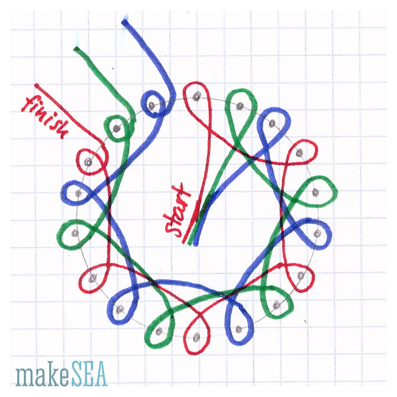
Brushless motor winding. A picture is worth hundreds of words. Here is a wiring diagram for the star configuration that I have found from the net. you are better to do this with great circumspection or it would be easily end up with a burned ESC. The first photo shown above is one group of the windings on the stator.

A brushed motor driver can be used to drive single phase brushless DC (BLDC) motors with a few minor modifications. In brushed motors, the brushes perform the commutation, physically changing the direction of the current as the motor rotates. In a BLDC system, the current direction is changed through the use of electronics.
On the outside, AirCore airplanes look like typical aircraft. Inside, though, is a BIG difference: the Power Cartridge. It contains a brushless motor, brushless ...

SINGLE SPEED MOTORS For delta ( ) wired motors For star ( ) wired motors Diagram DD1 Diagram DD2 Suggested wiring arrangement U1 U1 V1 V1 W1 W1 U2 U2 V2 V2 W2 W2 L1 L1 L2 L2 L3 L3 E E TWO-SPEED MOTORS with 2 separate windings (dual winding) High speed Red Leads Red Leads Black Leads Black Leads M 3~ Single speed only 3Ø WIRING DIAGRAMS U1 ...
Winding diagram depends on number of magnetpoles versus number of statorpoles. Manuals * Motor construction articles by Christo v.d. Merwe (nice motor colours ) www.bavaria-direct.co.za * Two motorwinding videos Keep in mind that CD-rom and (a)(d)lrk have different winding diagrams!!! Determined by #magnetpoles versus #statorpoles.

Motor winding similar to a brushless DC design; Manufacturing cost very low for mass production, when fully tooled; ... If the turn insulation fails in a form-wound stator winding, the motor will likely fail in a few minutes. Thus the turn insulation is critical to the life of a motor. Low voltage tests on form-wound stators, such as inductance ...
of the permanent magnet brushless AC motor according to the winding method are analyzed. A motor of the same size was designed by nite element method (FEM) simu- ... Winding diagram (a) Distributed winding diagram (phase A)(b) Concentric winding diagram (phase A) 5 International Journal of Pure and Applied Mathematics Special Issue 1809.

Brushless Dc Motor Winding Diagram Home Electrical Wiring, ... Muita gente tem-me perguntado como enrolar um motor Brushless, então resolvi postar aqui a ...

Recently, the flux-mnemonic permanent magnet brushless (FM-PMBL) motor is regarded as a promising traction motor for electric vehicles (EVs) due to its effective and efficient air-gap flux control.

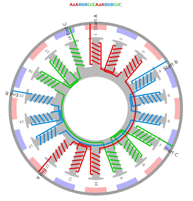
Here we see a winding diagram for a 3-phase AC induction motor or brushless PM motor (IPM), having 4 poles and 36 slots. This winding could in fact be used with any AC machine, including a synchronous reluctance motor or a wound-field synchronous motor or generator. In most respects it is a regular classical example, and the objective here is to review some of the features of the diagram and ...

BLDC motor stator winder coil winding machine from brushless dc electric motor diagram , source:youtube.com DRV8307 Brushless DC Motor Controller Rev A Three from brushless dc electric motor diagram , source:fdocuments.in. So, if you'd like to receive all these fantastic photos regarding (Brushless Dc Electric Motor Diagram
Brushless Motor Wiring Diagram Brushless Motor Winding Diagram 2eb99 Brushless Esc Wiring Diagram Digital Resources Industrial Grade Brushless Motors R4x Wiring Diagram Empire Amazon Com Zxtdr 48v 1800w Brushless Motor And Controller Mac 24 Volt 400 Watt Brushless Motor Wiring Manual From Rc Motor Diagram Wiring ...
You would expect that most existing brushless motors use slot/pole choices that produce the best performance but as we will find using computer analysis, this is not always the case. For example most (3) phase (4) pole brushless motors are designed using (12) slot laminations with a (3) slot pitch distributed winding.

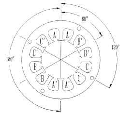
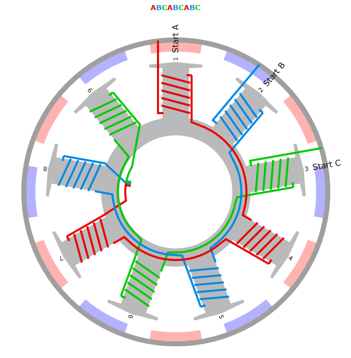
For this tutorial, I will be using Dynam E-Razor 450 Brushless Motor 60P-DYM-0011 (2750Kv). It is a Delta wound 8T (It means 8 turns) quad wind. The winding pattern described in this tutorial (called an ABC wind - ABCABCABC as you go around the stator) works for any brushless motor with 9 stator teeth and 6 magnets.

Brushless Dc Motor Winding Diagram Home Electrical Wiring, ... Muita gente tem-me perguntado como enrolar um motor Brushless, então resolvi postar aqui a ...

Brushless DC Motors K. Craig 5 • Windings - Consider the diagram of the elementary two-pole, single-phase stator winding. - Winding as is assumed distributed in slots over the inner circumference of the stator, which is more characteristic of the stator winding than is a concentrated winding.
Brushless Dc Motor Winding Diagram Home Electrical Wiring, ... Muita gente tem-me perguntado como enrolar um motor Brushless, então resolvi postar aqui a ...


0 Response to "40 brushless motor winding diagram"
Post a Comment