39 draw the moment diagram for the beam. follow the sign convention.
Draw the shear diagram for the beam. Follow the sign convention. (Figure 1) Draw the moment diagram for the beam. Follow the sign convention. 15 kN 10 kN/m 20 kN mm 2 m 2 m. Jan 19 2021 09:07 AM. 30.11.2021 · Draw the shear diagram for the beam follow the sign convention figure 1. beam. 1-137 16. 7-51 Complete Problem 7-51 from your Hibbeler textbook with all of the following modifications: (A) Replace the support reactions (pin at A and roller at B) with a single fixed support at point A (B) Determine the equations for internal Shear Diagram. e. R1 = R2 = W/2 = …
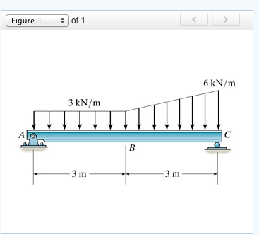
Problem 7.73 Consider the beam shown in (Figure 1). Follow the sign convention. Draw the shear diagram for the beam. Draw the moment diagram for the beam. Question: Problem 7.73 Consider the beam shown in (Figure 1). Follow the sign convention. Draw the shear diagram for the beam. Draw the moment diagram for the beam.
Draw the moment diagram for the beam. follow the sign convention.
Part A Draw the shear diagram for the beam. Follow the sign convention. (Figure 1) Click on "add vertical line off" to add discontinuity lines. Then click on "add segment button to add functions between the lines. Note 1- You should not draw an "extra" discontinuity line at the point where the curve passes the x-axis. 27.11.2021 · Draw the shear and moment diagrams for the beams shown below Answer to: Draw the shear diagram for the beam shown in the figure below. Follow the sign convention. By signing up, you'll get thousands of...
Draw the moment diagram for the beam. follow the sign convention.. These draw the shear and moment diagram for the beam can be used to easily determine the type size and material of a member in a structure so that a given set of loads can be supported without structural failure. Draw the shear diagram for the beam. Follow the sign convention. Figure 1 click on add vertical line off to add discontinuity lines. Part A Draw the shear diagram for the beam. Follow the sign convention. (Figure 1) Click on "add vertical line off" to add discontinuity lines. Then click on "add segment" button to add functions between the lines. Note - Make sure you place only one vertical line at places that require a vertical line. Draw the shear diagram for the beam. Follow the sign convention. (Figure 1) Click on "add vertical line off" to add discontinuity lines. Then click on "add segment" button to add functions between the lines. Note 1 - You should not draw an "extra" discontinuity line at the point where the curve passes the x-axis. And 2 draw the shear force and bending moment diagrams. Draw the shear diagram for the beam follow the sign convention figure 1. Figure 1 click on add vertical line off to add discontinuity lines. Show transcribed image text problem 770 draw the shear diagram for the beam. Neglect the weight of the beam.
Then, drawing the moment diagram using the shear sign convention gives a graph with what you have described as the "positive bending moment above the beam". The example in the book is easy to follow, put a single point load in the center of a simple beam and draw the diagrams by hand. Draw the moment diagram for the beam. Problem 770 draw the shear diagram for the beam. Then click on add segment button to add functions between the lines. Follow the sign convention. For drawing a bending moment diagram or bmd we use a positive sign for the sagging bending moment and a negative sign for the hogging bending moment as shown in ... Part a draw the shear diagram for the beam. Follow the sign convention. Figure 1 click on add vertical line off to add discontinuity lines. Then click on add segment button to add functions between the lines. Figure 1 part b draw the moment d. Draw the shear diagram for the beam. "usual" Civil Engineering sign convention for each of your diagrams (i.e. the sign convention we used in Lab #2). Show your results on the axes provided on the next page. Find internal shear and moment from A to B Make a cut at an arbitrary point between points A and B F.B.D of beam to left of cut, show unknown internal forces V and M in ...
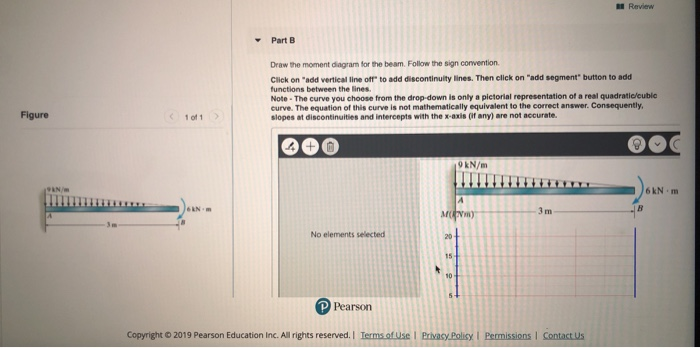
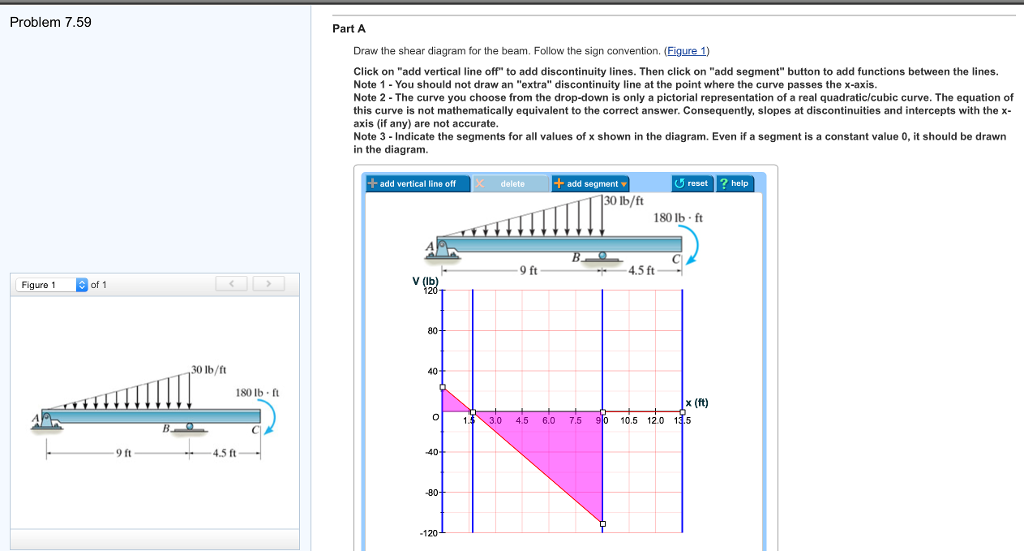
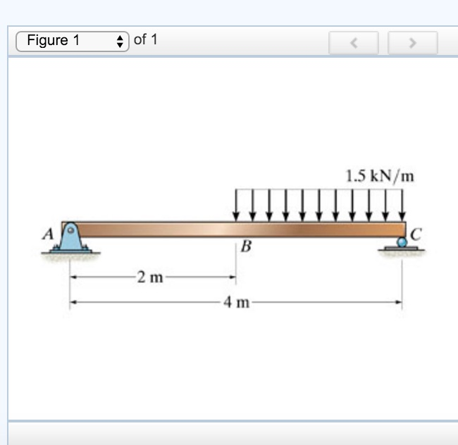
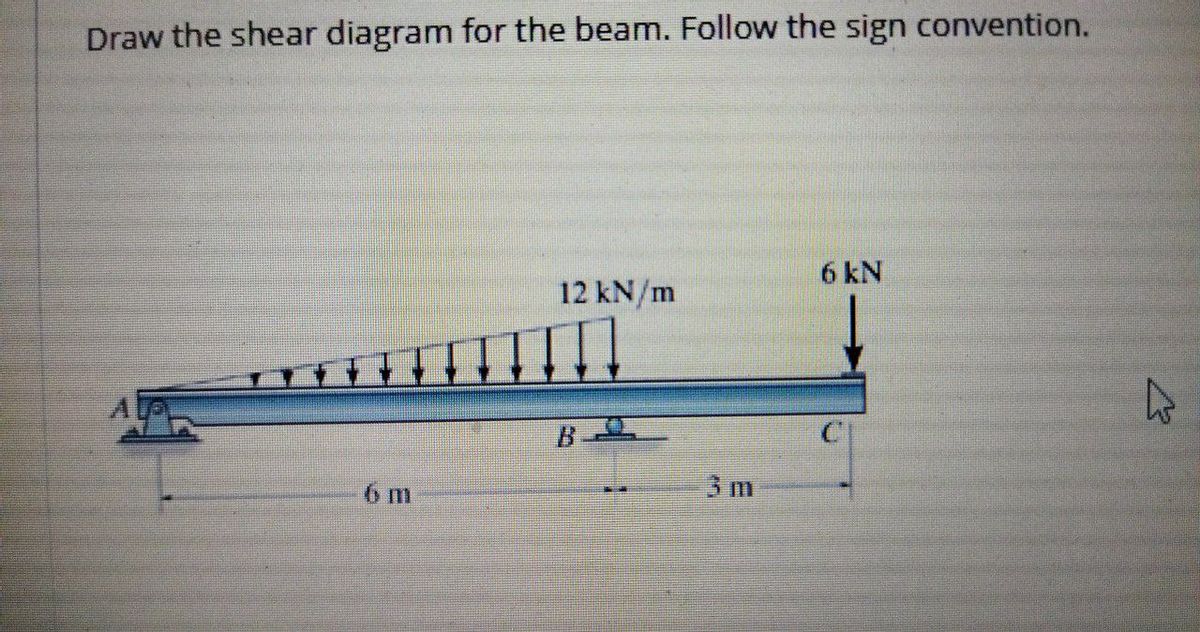
Note 1 - Draw a vertical line to denote local maximum or minimum. Note 2 - You should not draw an; Question: ws Figure 1 of 1 6 kN 12 kN/m - B 6 m 3 m Review Part B Draw the moment diagram for the beam. Follow the sign convention Click on "add vertical line off to add discontinuity lines. Then click on "add segment" button to add functions ... shear force and bending moment and also some basic concepts of strength of materials in our recent posts. We have already seen the various types of beams and different types of loads on beam during our previous posts. Today we will see here the sign conventions for shear force and bending moment diagram in subject of strength of materials with the help of this post. Problem 7.59 Part A Draw the shear diagram for the beam. Follow the sign convention. (Figure 1) Click on "add vertical line off" to add discontinuity lines. Then click on "add segment" button to add functions between the lines. Note 1- You should not draw an "extra" discontinuity line at the point where the curve passes the x-axis Note 2 The ... Answer to: Draw the shear and moment diagram for the beam. Follow the sign convention. By signing up, you'll get thousands of step-by-step...
The and plots are referred to as shear force diagram (SFD) and bending moment diagram (BMD) respectively. Example 7.2.1. Determine the and for the loaded beam shown in the figure. SOLUTION. 1- Draw the FBD of the beam. In the FBD, the directions of the unknown force and moment are assumed positive according to the member sign convention. 2- Solve the …

F.1 (b), the positive sign convention is (a) tension axial force, (b) shear forces that produce clockwise momentsand (c) bending moments that result in tension stresses in the interior frame fibers. The sign convention of F.1(b) can be seen to be equivalent to the beam sign convention rotating columns AB and CD to line up with beam BC. 27

Draw the shear diagram for the beam follow the sign convention figure 1. 3 15 9. 175. 5 18 Sh Eh ae tenens-v eo Yates n sn : Chem a0: sce (2) uusrso 8 Mien 0165 Nm km ms apn *7-89. per sq. 8 k ft. HibbelerThank you guys for Mechanical Engineering questions and answers. lb. 16 5. 0. Show transcribed image text problem 770 draw the shear diagram for the beam. At points …

Then draw the shear force diagram sfd and bending moment diagram bmd. For drawing a bending moment diagram or bmd we use a positive sign for the sagging bending moment and a negative sign for the hogging bending moment as shown in the figure below. Follow the sign convention. B if p 20 kn and l 6 m draw the sfd and bmd for the beam.

06.10.2012 · Draw a FBD of the beam section shown and labeling all forces and toque acting – including the shear force and bending moment (which act as an external force and torque at the point where we cut the beam.) (See Diagram – Section 1) Notice we have drawn the shear force and bending moment in their positive directions according to the defined sign convention …
Answer: As long as you are consistent it does not really matter which you consider positive and which you consider negative. To fall in line with general practice I recommend you consider sagging moment as positive and hogging moment as negative. Draw the BM diagram consistently on the tension ...

01.12.2021 · Determine the shear diagram for the simply supported beam. Products. Determine the shear diagram for the simply supported beam Posts & Pages ...
When the shear diagram is decreasing, the moment diagram is concave downward. Sign Convention The customary sign conventions for shearing force and bending moment are represented by the figures below. A force that tends to bend the beam downward is said to produce a positive bending moment. A force that tends to shear the left portion of the ...

beam from the left hand end and summing up the areas of shear force diagrams using proper sign convention. xThe process of obtaining the moment diagram from the shear force diagram by summation is exactly the same as that for drawing shear force diagram from load diagram.

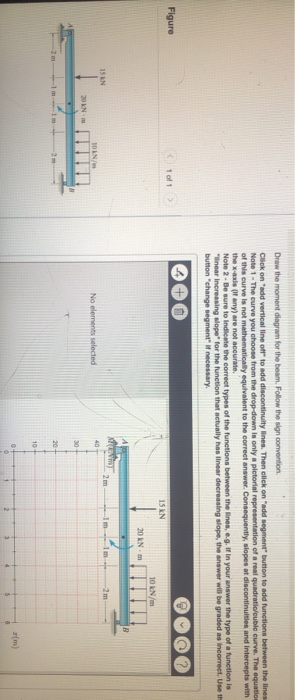
Problem 7.84 Draw the moment diagram for the beam. Follow the sign convention. Click on "add vertical line off" to add discontinuity lines. Then click on "add segment" button to add functions between the lines. Note 1 - Draw a vertical line to denote local maximum or minimum.
Draw the shear diagram for the beam follow the sign convention figure 1. This is done using a free body diagram of the entire beam. Figure 1 draw the moment diagram for the beam. 1 answer below. Then click on add segment button to add functions between the lines. Draw the shear and moment diagrams for the beam.

The three most prominent internal forces in structural analysis calculations are the bending moment, shear force, and axial force. It is very common for people to define and state their sign convention before proceeding with any structural analysis problem. This is mainly due to variations in the selection of positive and negative coordinates.

F.1 (b), the positive sign convention is (a) tension axial force, (b) shear forces that produce clockwise moments and (c) bending moments that result in tension stresses in the interior frame fibers. The sign convention of F.1(b) can be seen to be equivalent to the beam sign convention rotating columns AB and CD to line up with beam BC.
Draw the shear diagram for the beam. Compute the reaction forces and moments. Assume the support at is a pin. Follow the sign convention. Then click on add segment button to add functions between the lines. If there is an upward force ie a support then the sfd will start at this force above the x axis.
Draw the shear diagram for the beam follow the sign convention figure 1 on add vertical line off to add discontinuity lines lecture note course code bce 306 structural analysis 2 3 under revision disclaimer this document does not claim any originality and cannot be used as a substitute for prescribed textbooks the information.

Draw The Moment Diagram For The Beam Follow The Sign Convention The reactions have been determined as shown on the beam’s free-body diagram, Fig. 5 m--1. Hibbeler. [Nov /Dec 2016] X SFD: x x x2 SF atXX 22 x 0 SF at B 0 x SF at A 2 "" " " B A x (N/m) X " Draw the shear diagram for the beam. Again, if you make this cut, you can look at this region here, um, and …
Consider the beam shown in (Figure 1) . Follow the sign convention. Draw the shear diagram for the beam. Draw the moment diagram for the beam. Fundamental Problem 4.13 Considor tho beam shown in Eguro 10. Follow tho sign convention. 2 m 2 m Part A...
Follow the sign convention 100 even more pictures by bevitahealthy on august 10 2018 draw the shear diagram for the beam. The sign conventions used for representing various quantities in solid mechanics or mechanics of materials have a lot of importance and determine the way most of the important relations formulae procedures for calculation ...

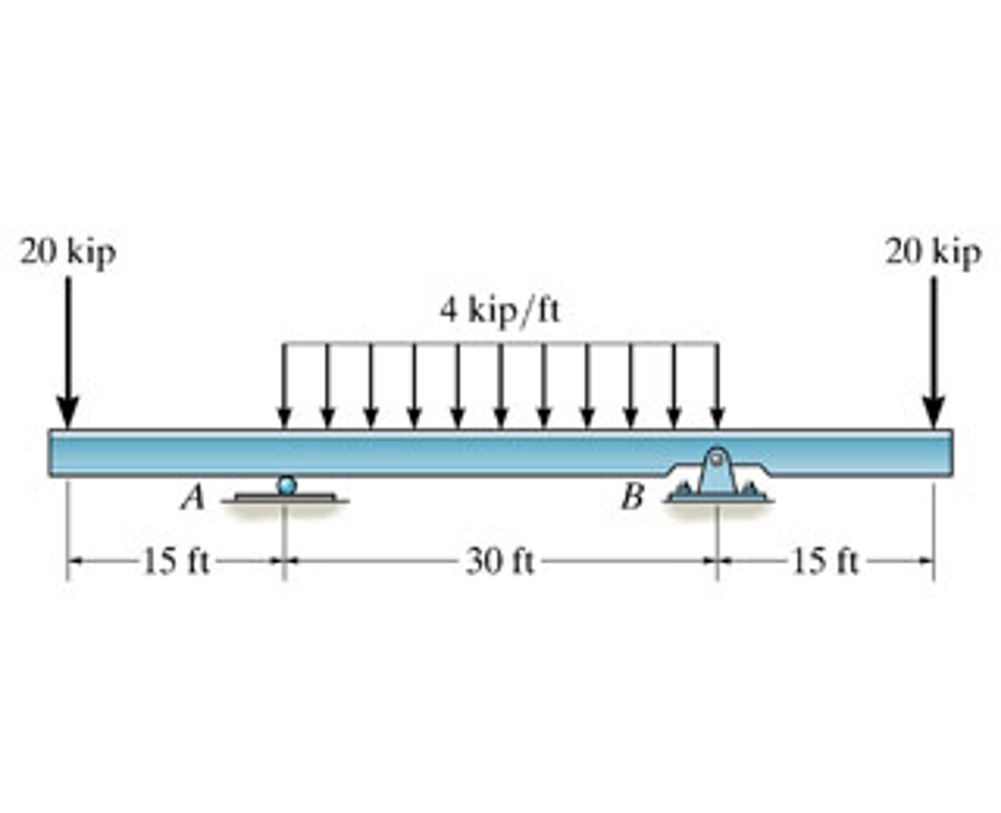
Equations of Equilibrium: Referring to the free-body diagram of the beam shown in Fig. a, a Shear and Moment Diagram: As shown in Figs. b and c. A y = 1000 lb +c©F y = 0; A y + 1000 - 400 - 200(6) - 400 = 0 B y = 1000 lb +©M B y(6) + 400(3) - 200(6)(3) - 400(9) = 0 A = 0; 6-39. Draw the shear and moment diagrams for the double overhanging ...
Answer to: Draw the shear diagram for the beam shown in the figure below. Follow the sign convention. By signing up, you'll get thousands of...

27.11.2021 · Draw the shear and moment diagrams for the beams shown below

Part A Draw the shear diagram for the beam. Follow the sign convention. (Figure 1) Click on "add vertical line off" to add discontinuity lines. Then click on "add segment button to add functions between the lines. Note 1- You should not draw an "extra" discontinuity line at the point where the curve passes the x-axis.


0 Response to "39 draw the moment diagram for the beam. follow the sign convention."
Post a Comment