38 commercial defrost timer wiring diagram
I am trying to install a defrost timer on a commercial ... I am trying to install a defrost timer on a commercial freezer. It is a 220 defrost-o-matic replacement. I have it so that the compressor starts and stops ok but can not figure out how or maybe I should say where to hook up the defrost heater. Could you sketch me a simplified wiring diagram and tell me how to test to make sure it is right. refrigerator defrost timer wiring diagram - Wiring Diagram ... Defrost Timer W10822278 Official Whirlpool Part Fast Shipping Partselect. Sketch Wiring Diagram Of Dwelling House Pour Android Téléchargez L. Precision Multiple Controls Official Website Your Source For Energy Saving Photocontrols. China Supco Heavy Duty 8 Hours 25 Minutes Refrigerator Tmdc Defrost Timer 825 1 And.
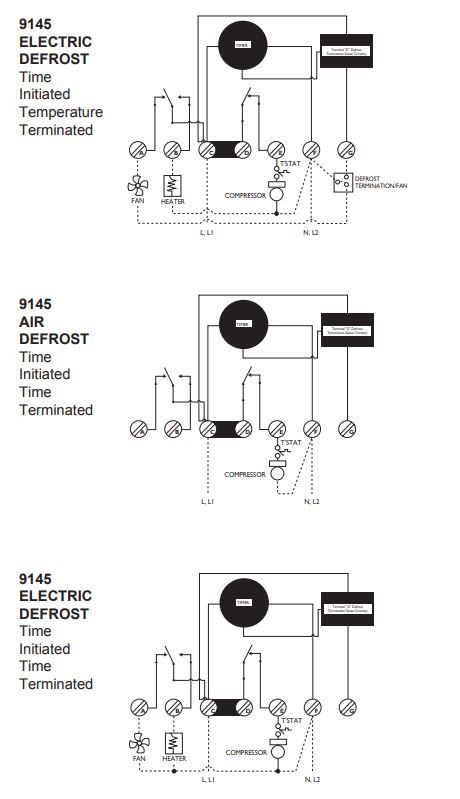
Paragon Timer Wiring Diagram - schematron.org Paragon 8145 20 Wiring Diagram Please download these Paragon Timer Wiring Diagram by using the download button. DEFROST TIMERS An ISO - Certified Company Features and Benefits The Paragon® and Universal Defrost Timers are the only multi-voltage defrost timers engineered to refrigeration standards.
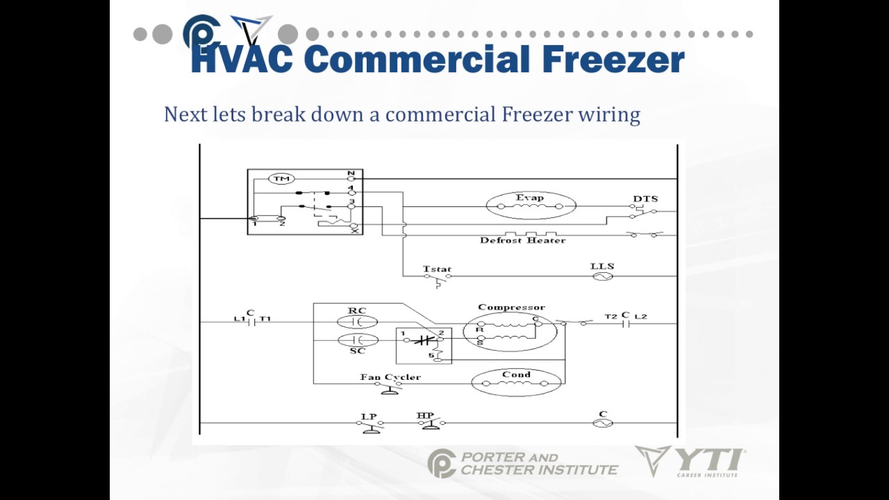
Commercial defrost timer wiring diagram
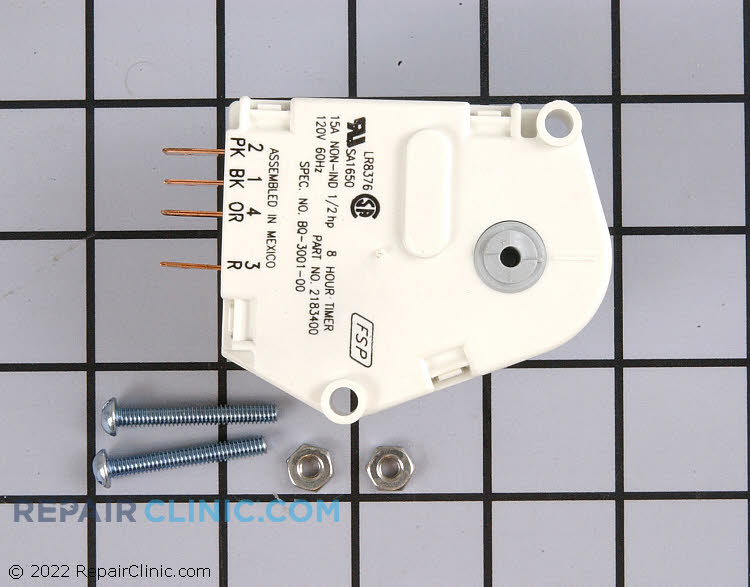
PDF Defrost Time Controls / HVAC/R - Neuco The defrost timer shall be housed in a UL Type 3R indoor/outdoor plastic enclosure. The relay output will be rated for 40 A Resistive, 2 HP @ 240 VAC. Defrost terminations to be by time (or by a remote temperature or pressure switch). For carry-over, the time controls shall have 2500-Hour reserve carry-over from a self-recharging battery. PDF Commercial Refrigeration Defrost Controls - Supco Commercial Refrigeration Defrost Controls SEALED UNIT PARTS CO., INC. PO Box 21, 2230 Landmark Place, Allenwood, NJ 08720 USA Phone 732-223-6644 • Fax 732-223-1617 • info@supco.com Commercial Refrigeration Defrost Controls Designed to meet a wide variety of customer requirements. Amazon.com: Mengfan Refrigerator Defrost Timer TMDJ830RB9 ... Mengfan Refrigerator Defrost Timer TMDJ830RB9 for GE WR9X502. . This fits your . Make sure this fits by entering your model number. Designed to fit specific General Electric manufactured refrigerator models including Hotpoint and RCA. 4 Terminals are on the timer, numbered 1,4,3,2. Frequency 6 hour 25 minute, which means every 6 hours it turns ...
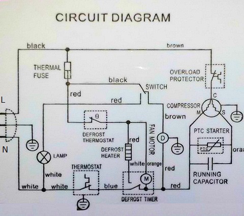
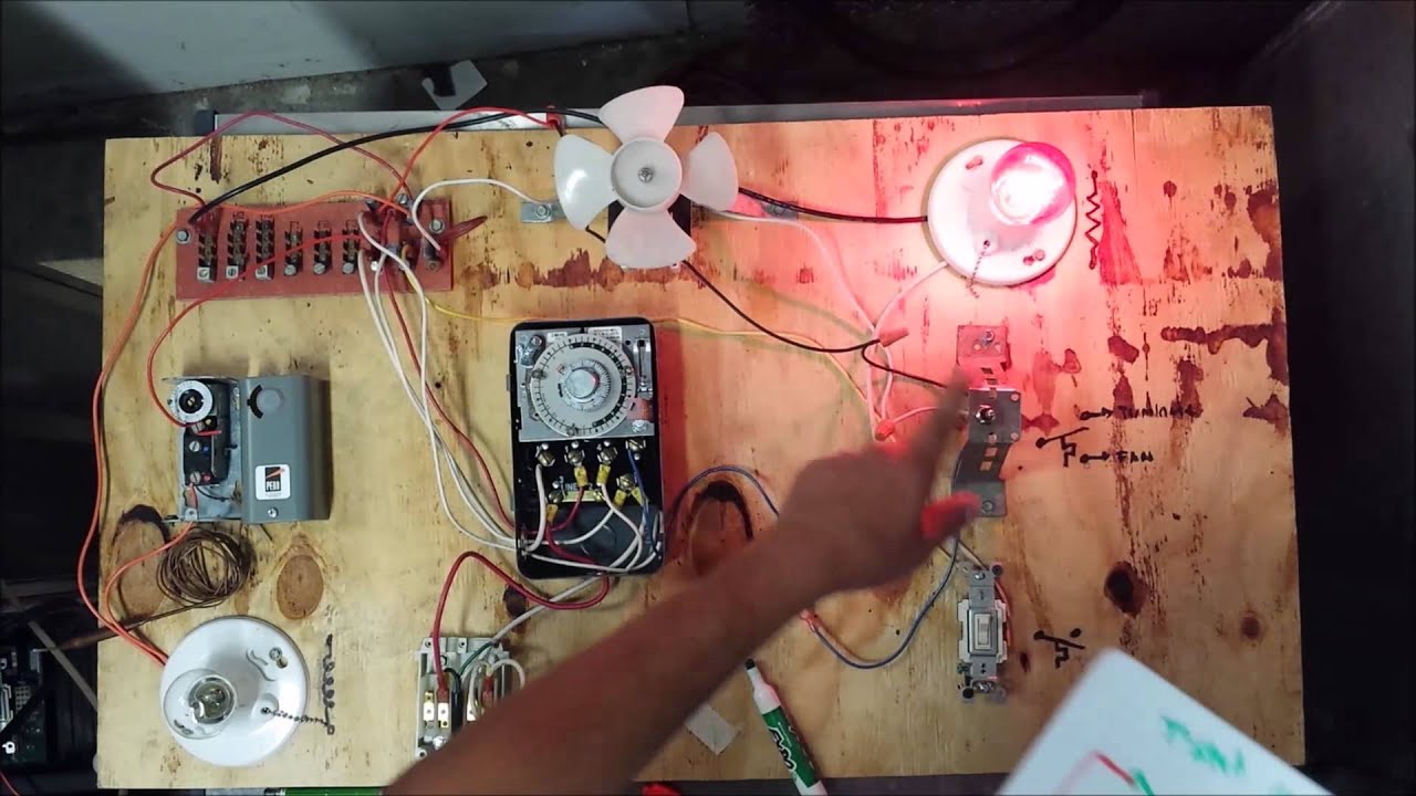
Commercial defrost timer wiring diagram. Refrigerator Repair and defrost timer wiring diagram - YouTube In this video you can learn about the defrost timer wiring diagram of a frost free refrigerator and circuit diagram Step by step details about the function o... Casual Paragon Defrost Timer Wiring Diagram Nissan Rogue ... Grasslin defrost timer wiring diagram book of paragon 20 dia arcnx paragon defrost timer wiring diagram clock and freezer to 20 paragon defrost timer wiring diagram fresh 20 questions answers with. A wiring diagram typically gives info regarding the loved one setting and plan of gadgets as well as terminals on. PDF COMMERCIAL REFRIGERATOR & FREEZER SERVICE MANUAL (CFD Units) As well as the automatic defrost function, a manual defrost can be enabled, if the temperature conditions allow, by pressing the" button for more than 5 seconds. PDF Service Manual - HOSHIZAKI B. Refrigeration Circuit Diagram 1. Refrigerator and Freezer Evaporator Fans (1, 2, or 3 depending on model) Evaporator Compressor Drier Condenser Fan Condenser Freezer and Prep Table Models: Defrost Heater, Defrost Safety Thermostat, and Defrost Thermistor Cabinet Thermostat Bulb Capillary Tube High-Pressure Switch
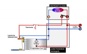
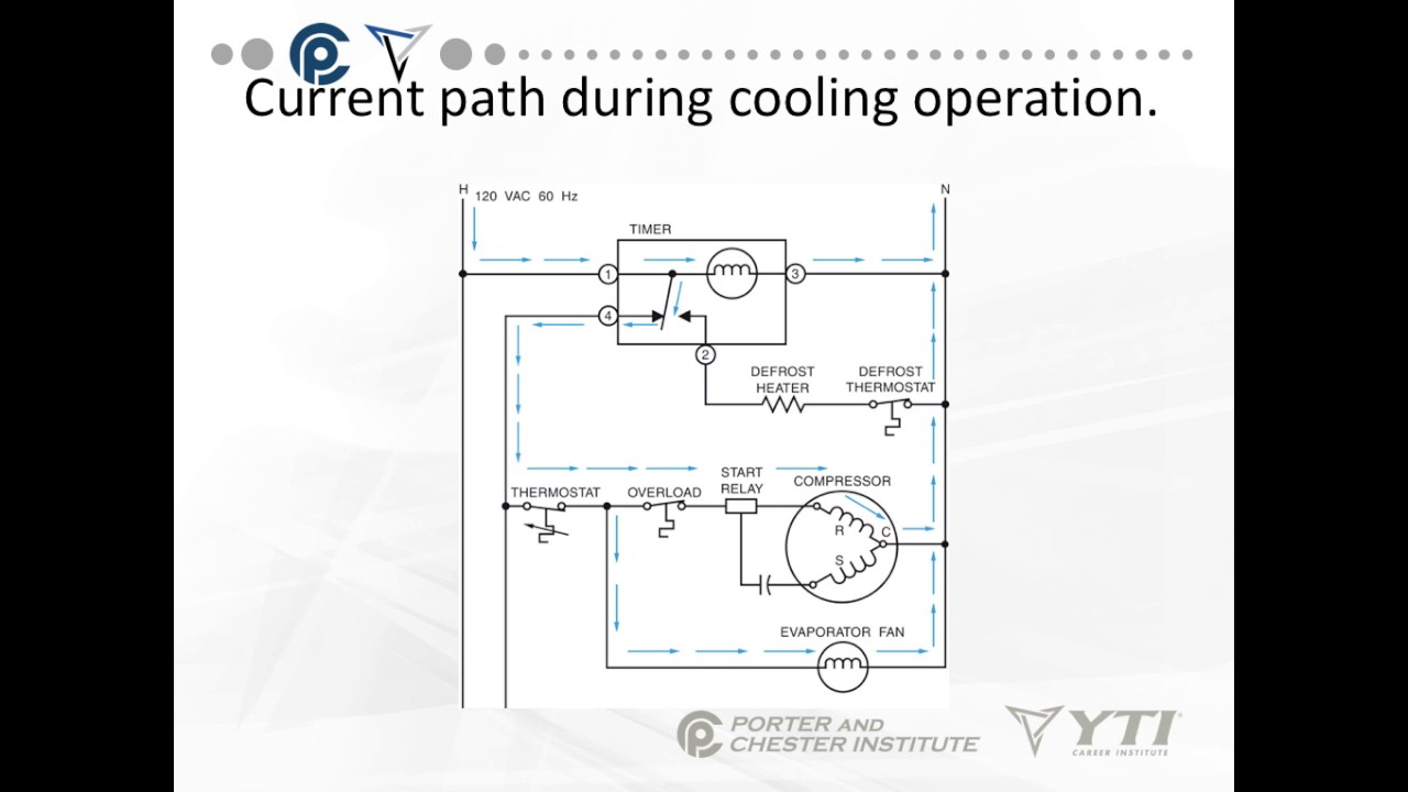
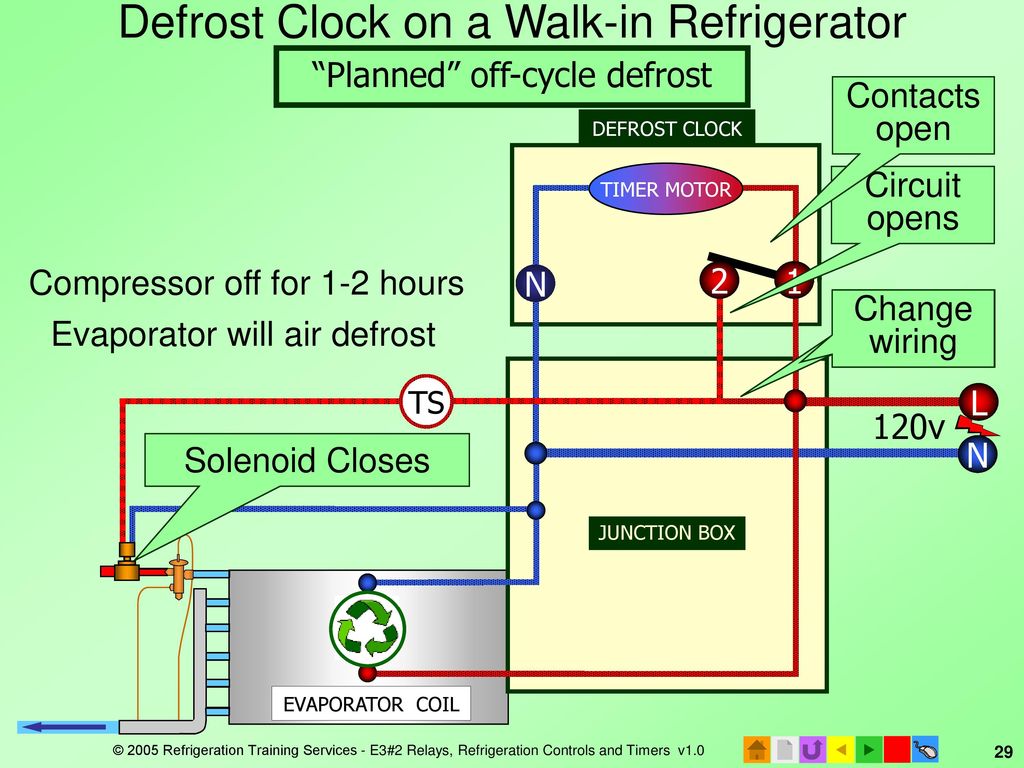
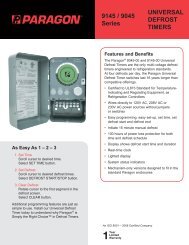
PDF 8000 MECHANICAL Series DEFROST TIMER - Everwell Parts 2. Set Defrost Insert pin(s) to desired defrost time(s) on outer dial. 3. Set Defrost Duration Move copper pointer to desired duration of defrost time on inner dial. Install our Commercial Defrost Controls today to understand why Paragon® is Simply the Right Choice™ in Defrost Timers. An ISO 9001 - 2008 Certified Company 1 Year Limited ... Walk In Freezer Defrost Timer Wiring Diagram At the condenser contactor, the defrost timer is wired in series with the high pressure switch and the low Me neither, even have some in freezers. Defrost Timer Controls. - Series Defrost Retail store walk-in coolers and freezers. • Boiler operating Typical line voltage wiring diagram. 3. Determine. PDF Commercial Refrigeration Temperature and Defrost Controls Typical line voltage wiring diagram 3. Determine location of sensor Troubleshooting Error Messages • E1 Not in program mode - If the E1 message appears when no keys are being pressed, replace the control. • E2 Settings are not properly stored in memory - Check all settings and correct if necessary. Typical wiring for defrost on a single evaporator freezer ... Wiring for a single evap freezer system or reach in freezer. Any questions or comments Feel free to ask in the comment section . Thanks for watching 👍. ...
Walk In Freezer Defrost Timer Wiring Diagram In a common wiring diagram for a time-initiated, temperature-terminated Normally closed contacts of the defrost timer are wired in series. OUTDOOR WALK-IN COOLERS AND FREEZERS . Wiring Diagram - Freezer ½ to 2 HP Single Phase. .. Set the correct time of day on the defrost timer. Defrost Timer Controls. Freezer Defrost Timer Wiring Diagram Step 3: Test the defrost timer with a VOM set to the RX1 scale. Clip one probe of the VOM to each defrost timer -- not motor -- wire, and turn the timer control. Defrost Timer Controls. - Series Defrost Timers Retail store display freezers and reach-in coolers Typical line voltage wiring diagram. 3. Determine . DEFROST. TIMER. Shop BTP4520 - Electromechanical Defrost Timer - IRP - URI These timers are adjustable from one to six cycles per day. A minimum of four hours is required between successive operations. Defrost duration ranges from 4 to 110 minutes in 2 minute increments and is easily adjustable. Time initiation, temperature or pressure termination; Contact rating: 40 amps resistive/pole Paragon Defrost Timer Wiring Diagram Paragon Defrost Timer Wiring Diagram On the timer wheel, choose a defrost cycle starting time. 2. Slide the the wiring diagram chosen. . Robertshaw®, Paragon® and Uni-Line® are trademarks of. Defrost Timer Controls. - Series Defrost Typical line voltage wiring diagram. 3. Determine Paragon® Universal Defrost Timer (UDT). Why do I need a.
Defrost Timer Product Sheet.indd
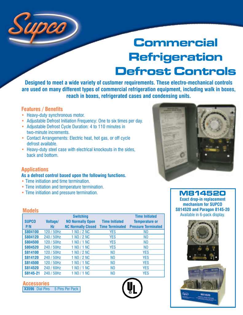
Supco S814100--COMMERCIAL DEFROST CONTROL Designed to meet a wide variety of customer requirements. These electro-mechanical controls are used on many different types of commercial refrigeration equipment, including walk in boxes, reach in boxes, refrigerated cases and condensing units. Features/Benefits
Introduction to refrigeration defrost methods Part I
Commercial Defrost Timer Wiring Diagram - Using Defrost ... If your meter reads the proper voltage, then the timer board is good and is supplying power to the gear motor relay or circuit. Check your wiring diagram to determine which voltage should be present at terminal eight. Depending on the model you are working on, this terminal could either be a line voltage or a controlled voltage circuit.

No frost refrigerator D frosting timer function and ...
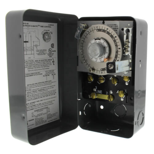
8141-20 - Paragon 8141-20 - 208/240V Defrost Timer Paragon 8141-20 - 208/240V Defrost Timer - Designed for commercial freezers and refrigerators, Paragon commercial defrost controls provide automatic defrost capability. They accommodate various types of defrost systems including electric defrost heaters, hot gas and compressor off cycle. Time initiated, temperature or pressure terminated High ...
120V Defrost Timer
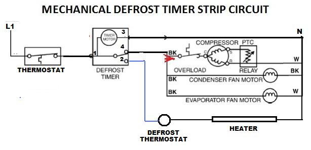
PDF Paragon 8045-20 defrost timer wiring diagram Description: Freezer Defrost Timer Wiring 220V Commercial Freezer Defrost Timer with Walk In Freezer Defrost Timer Wiring Diagram, image size 598 X 452 px, and to view image details please click the image.. The most common form of defrosting a freezer's unit cooler is done by control for the evaporator is wired to terminal "X" on the defrost timer.

Kenmore refrigerator won't get cold enough - DoItYourself.com ...
8141-00m Wiring Diagram Uni-Line Applications and Wiring Diagrams. MECHANICAL.Paragon - V Defrost Timer - Designed for commercial freezers and refrigerators, Paragon commercial defrost controls provide automatic defrost capability. They accommodate various types of defrost systems including electric defrost heaters, hot gas and compressor off cycle.
Reading wiring diagrams: How the Defrost Cycle works in a ...
Star Delta Wiring Diagram With Timer Pdf - Wiring Diagram Wiring diagrams. Star delta wiring diagram with timer page. 2 4 6 2 4 6 1 3 5 star delta main overload v2 u2 w2 u1 v1 w1 s d m l1 l2 l3 n supply 230v control 400v control 1 3 5 02 01 14 13 14 13 a2 a2 a2 a1 a1 4 3 a1. Power circuit of star delta starter. Star delta starters open type version. Circuit diagram with timer pdf free star delta control.
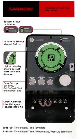
PARAGON COMMERCIAL DEFROST TIMER DIGITAL
Amazon.com: Mengfan Refrigerator Defrost Timer TMDJ830RB9 ... Mengfan Refrigerator Defrost Timer TMDJ830RB9 for GE WR9X502. . This fits your . Make sure this fits by entering your model number. Designed to fit specific General Electric manufactured refrigerator models including Hotpoint and RCA. 4 Terminals are on the timer, numbered 1,4,3,2. Frequency 6 hour 25 minute, which means every 6 hours it turns ...

Defrost Time & Temperature - HVAC School
PDF Commercial Refrigeration Defrost Controls - Supco Commercial Refrigeration Defrost Controls SEALED UNIT PARTS CO., INC. PO Box 21, 2230 Landmark Place, Allenwood, NJ 08720 USA Phone 732-223-6644 • Fax 732-223-1617 • info@supco.com Commercial Refrigeration Defrost Controls Designed to meet a wide variety of customer requirements.
Commercial Refrigeration Temperature and Defrost Controls
PDF Defrost Time Controls / HVAC/R - Neuco The defrost timer shall be housed in a UL Type 3R indoor/outdoor plastic enclosure. The relay output will be rated for 40 A Resistive, 2 HP @ 240 VAC. Defrost terminations to be by time (or by a remote temperature or pressure switch). For carry-over, the time controls shall have 2500-Hour reserve carry-over from a self-recharging battery.

Core Refrigeration: Domestic Defrost Timer

Defrost termination / fan delay operation
Freezer Defrost Timer Live Operation
HVAC-Talk: Heating, Air & Refrigeration Discussion
Defrost Timer
REFRIGERATION
Defrost Time Controls / HVAC/R Defrost Time Controls / HV AC/R
Core Refrigeration: Domestic Defrost Timer
Core Refrigeration: Refrigeration Wiring

DEFROST TIMER CIRCUITS SCHEMATIC DIAGRAM SAMPLE AND ...

Description: The non frost refrigerator diagram is very easy ...
Defrost Time Controls / HVAC/R Defrost Time Controls / HV AC/R

Unique Walk In Freezer Defrost Timer Wiring Diagram | Walk in ...
Commercial Refrigeration Temperature and Defrost Controls
REFRIGERATION
REFRIGERATION

Defrosting Refrigeration Systems: Keep it Short and Sweet ...

Types Of Automatic Pumpdown Control Systems | ACHR News
E3 HVACR Controls and Devices - ppt download
Defrost Time Controls / HVAC/R Defrost Time Controls / HV AC/R

No frost | D-frost Timer Diagram - FULLY4WORLD

Defrosting Refrigeration Systems: Keep it Short and Sweet ...
PARAGON COMMERCIAL DEFROST TIMER DIGITAL
MECHANICAL DEFROST TIMER 8000 Series - Uni-Line
Older Frigidaire defrost timer - DoItYourself.com Community ...
Introduction to refrigeration defrost methods Part I

Invensys Controls - CD104 Commercial Defrost Timer
Commercial Walk-in Freezer Heatcraft let090bswj Repair - not ...
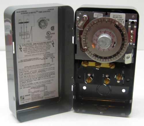
Paragon Commercial Defrost Timer | McCombs Supply Co | 8045-00
0 Response to "38 commercial defrost timer wiring diagram"
Post a Comment