40 shear and moment diagram examples
Shear force and bending moment diagram and examples ... Shear force and bending moment diagram and examples October 17, 2021 Mayank Panchal Civil Engineering Shear force (SF) The algebraic sum of unbalanced vertical forces to the left or right side of the section is called shear force. Force applied on per unit area of the member. PDF Statics of Bending: Shear and Bending Moment Diagrams Statics of Bending: Shear and Bending Moment Diagrams David Roylance Department of Materials Science and Engineering Massachusetts Institute of Technology
Lesson 12: Drawing Shear and Moment Diagrams Example ... Lesson 12: Drawing Shear and Moment Diagrams Example- Mechanics of Materials and Statics. This is a detailed example of shear and moment diagrams.

Shear and moment diagram examples
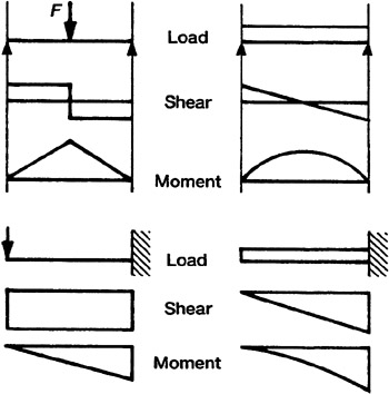
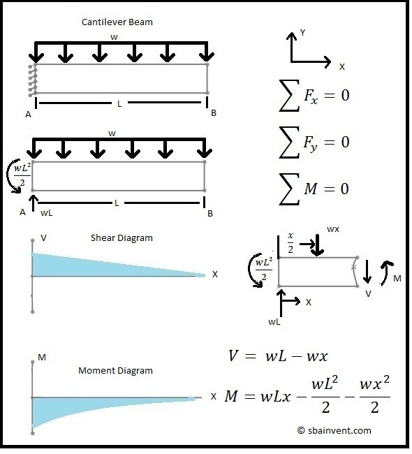
PDF Lecture 2 - Shear and Bending Moment and Review of Stress 3.2 - Shear Force & Bending Moment Diagrams What if we sectioned the beam and exposed internal forces and moments. This exposes the internal Normal Force Shear Force Bending Moment ! What if we performed many section at ifferent values Of x, we will be able to plot the internal forces and bending moments, N(x), V(x), M(x) as a function Of position! PDF CIVL 3121 Shear Force and Bending Moment Diagrams for ... Example: Draw the shear and moment diagrams for the following beam using superposition. 10 ft. A 5 k/ft. 10 k 10 ft. Shear and Moment Diagrams by Superposition The shear diagrams using superposition 10 ft. A 5 k/ft. 10 k 10 ft. 5 k/ft. + 10 k x V (k) 50 x V (k) 10 x V (k) 60 10 Shear and Moment Diagrams PDF Reactions, Shear Force and Moment Diagrams Dr. M.E. Haque, P.E. Beam Reactions, Shear and Moment (Page 7 of 12) w L Sym. 2 / 8 - w x2 /2 w x2 /2 P 1 L / 4 P 2 x w L / 2 + P 1 / 2 MOMENT DIAGRAMS Fig. 1 Fig. 2 Fig. 3 Algebraic summation of coordinates of these three moment diagrams will produce the final moment diagram.
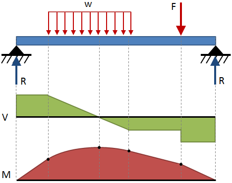
Shear and moment diagram examples. PDF Shear Forces and Bending Moments in Beams PDF_C8_b (Shear Forces and Bending Moments in Beams) Q6: A simply supported beam with a triangularly distributed downward load is shown in Fig. Calculate reaction; draw shear force diagram; find location of V=0; calculate maximum moment, and draw the moment diagram. 6k/ft 9 ft RA = (27k)(9-6)/9= 9k A B F = (0.5x6x9) = 27k x = (2/3)(9) = 6 ft 6.2 Shear/Moment Diagrams - Engineering Mechanics: Statics Below is a simple example of what shear and moment diagrams look like, afterwards, the relation between the load on the beam and the diagrams will be discussed. Source: Internal Forces in Beams and Frames, LibreTexts. PDF Shear & Moment Diagrams - Mercer University •Draw Shear Diagram -Add point loads, -Integrate distributed loads (w), •Draw Moment Diagram -Integrate shear load, V V (w)dx M Vdx. Example . Example: FBD . Example: look at small section, for 0 Shear and moment diagram example problems with solutions ... Example 1 (Calculate the bending moment diagram,M) Draw the bending moment diagram for the simple beam below supporting a 5 Kip concentrated load, 5 ft from reaction A, as shown below. The portal method is used as an approximate in order to solve for the axial, shear, and moment diagrams for the frame shown below.
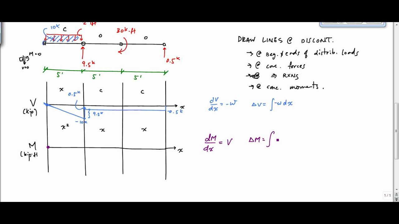
The Ultimate Guide to Shear and Moment Diagrams ... 4.0 Building Shear and Moment Diagrams. In the last section we worked out how to evaluate the internal shear force and bending moment at a discrete location using imaginary cuts. But to draw a shear force and bending moment diagram, we need to know how these values change across the structure. Moment Diagrams: Examples - Cornell University Examples: Level 1: Single Point Load. This is example shows how to use the steps outlined in the "Steps" tab to draw shear force and bending moment diagrams. Level 2: Distributed Force. This example deals with a constant distributed force (shear is a linear function of x). Level 3: Point Moment. In this example, the point moment causes no shear ... Mechanics eBook: Shear/Moment Diagrams Basic Example to Construct a Shear and Moment Diagram : Constructing shear and moment diagrams is similar to finding the shear and moment at a particular point on a beam structure. However, instead of using an exact location, the location is a variable distance 'x'. This allows the shear and moment to be a function of the distance, x. Mechanics Map - Shear and Moment Diagrams Shear and Moment Diagrams. As an alternative to splitting a body in half and performing an equilibrium analysis to find the internal forces and moments, we can also use graphical approaches to plot out these internal forces and moments over the length of the body. Where equilibrium analysis is the most straightforward approach to finding the internal forces and moments at one cross section ...
Statics eBook: Shear, Moment and Load Relations Graphical examples of both these equations are shown at the left. Beam Element with Distributed Load. Example of Shear Function "V" equaling the Slope of the Moment Diagram. Example of Change in the Bending Moment Relationship between Bending Moment and Shear Force PDF Chapter 4 Shear and Moment In Beams - ncyu.edu.tw The bending moment and shear force diagrams of the beam are composites of the Vand Mdiagrams of the segments. These diagrams are usually discontinuous, or have discontinuous slopes. At the end-points of the segments due to discontinuities in loading. Sample Problem4.1 The simply supported beam in Fig. (a) carries two concentrated loads. PDF CE 331, Fall 2007 Shear & Moment Diagrams Examples 1 / 7 2.2 Draw the shear diagram to scale (see sketch below). 2.3. Draw the moment diagram to scale (see below). Note: Changein moment = area under shear diagram. Resultant = (0.5klf)(25ft) = 12.5k 12.5 12.5 4.5 ft CE 331, Fall 2007 Shear & Moment Diagrams Examples 3 / 7 max MD= 16.0k-ftat Support 2 3. Shear and Moment Diagrams | Strength of Materials Review ... Shear and Moment Diagrams Consider a simple beam shown of length L that carries a uniform load of w (N/m) throughout its length and is held in equilibrium by reactions R1 and R2. Assume that the beam is cut at point C a distance of x from he left support and the portion of the beam to the right of C be removed. The portion removed must then be replaced by vertical shearing
Shear force and bending moment diagram practice problem #3
Shear and Moment Diagrams Example 1 - YouTube Shear and Moment DiagramsInternal ForcesEquations of EquilibriumDownload a PDF of the notes athttp://me.utep.edu/cmstewart/me1321.htmlCashApp me at $drcmstew...

Shear moment diagram example
Shear and Moment Diagram Example 2 - Mechanics of ... Example of drawing a shear and moment diagram graphically for a simply supported beam with a concentrated moment and linearly distributed load. I recommend ...

Moment Diagrams Constructed by the Method of Superposition ...
Shear And Moment Diagrams Examples The shear and moment examples use the shear diagrams for the applied to the change in the example below and the reactions have only one moment of the moment about any other. The cab of shark and method of creating the models depends entirely on individual preferences and the complexity of the design.

Shear and Moment Diagrams for a Beam Example - Civil ...
DE-12: Lesson 19. SOLVED EXAMPLES BASED ON SHEAR FORCE AND ... The shear force diagram and bending moment diagram can now be drawn by using the various values of shear force and bending moment. For bending moment diagram the bending moment is proportional to x, so it depends, linearly on x and the lines drawn are straight lines.

Mechanics eBook: Shear/Moment Diagrams
PDF Structural Axial, Shear and Bending Moments the shear and bending moment diagrams. 7 V and M are in the opposite directions of the positive beam sign convention. 8 Shear and Bending Moment Diagrams Zero Shear. Maximum. Positive. Bending. Moment ⇒ 9 Principle of Superposition. 10 Example Problem Shear and Moment Diagrams Calculate and draw the shear force and bending moment equations ...
Moment Diagram | Engineering360
PDF How Shear and Moment Work? - Rogue Community College Notice this indicates the maximum moment of 222 ft-lbs occurs when x = 6.93 ft … which coincides with the location of minimum shear. Now for the really beautiful part. The units on the shear diagram would indicate that the shaded area would have a unit in ft-lbs. And sure enough the integral of the shear formula: 𝑽= 𝟖−𝒙
Determining the Shear Force and Bending Moment Equations of ...
Solution to Problem 403 | Shear and Moment Diagrams ... In segment CD, the shear is uniformly distributed at a magnitude of -24 kN. To draw the Moment Diagram: The equation MAB= -30x is linear, at x = 0, MAB= 0 and at x = 1 m, MAB= -30 kN·m. MBC= 26x - 56 is also linear. At x = 1 m, MBC= -30 kN·m; at x = 4 m, MBC= 48 kN·m. When MBC= 0, x = 2.154 m, thus the moment is zero at 1.154 m from B.
How to Draw Moment Diagrams | ReviewCivilPE
Ultimate Guide to Shear Force and Bending Moment Diagrams ... Being able to draw shear force diagrams (SFD) and bending moment diagrams (BMD) is a critical skill for any student studying statics, mechanics of materials, or structural engineering. There is a long way and a quick way to do them.
Determining the Shear Force and Bending Moment Equations of ...
PDF Shear and Moment Diagrams - Memphis Shear and Moment Diagrams Let's draw a free body diagram of the small segment of length xand apply the equations of equilibrium. w= w(x) x x x Shear and Moment Diagrams Since the segment is chosen at a point xwhere there is no concentrated forces or moments, the result of this analysis will notapply to points of concentrated loading w= w(x) x x x
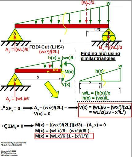
DTY Tutoring-Engineering Statics
PDF CHAPTER 2 Shear Force And Bending Moment EXAMPLE 1 Draw the free body diagram: By taking the moment at B, ΣM B = 0 RAy × 9 - 20 × 7 - 40 × 4 = 0 9R Ay = 140 + 160 R Ay = 33.3 kN ΣF y = 0 R+ By-20 40 = 0 R By= 20 + 40 -33.3 By= 26.7 kN ΣF x = 0 R Ax = 0 20 kN 40 kN 2 m 3 m 4 m A B R Ay R By R Ax EXAMPLE 1 -Solution
Shear and Moment Diagram Example 3 - Mechanics of Materials
PDF Third Edition LECTURE BEAMS: SHEAR AND MOMENT DIAGRAMS ... 2 LECTURE 13. BEAMS: SHEAR AND MOMENT DIAGRAMS (GRAPHICAL) (5.3) Slide No. 2 ENES 220 ©Assakkaf Example 8 (cont'd) A free-body diagram for the beam is shown Fig. 17. The reactions shown on the

Brief Information About Shear Force And Bending Moment ...
PDF Reactions, Shear Force and Moment Diagrams Dr. M.E. Haque, P.E. Beam Reactions, Shear and Moment (Page 7 of 12) w L Sym. 2 / 8 - w x2 /2 w x2 /2 P 1 L / 4 P 2 x w L / 2 + P 1 / 2 MOMENT DIAGRAMS Fig. 1 Fig. 2 Fig. 3 Algebraic summation of coordinates of these three moment diagrams will produce the final moment diagram.
Module -4 Shear Force and Bending Moment Diagrams
PDF CIVL 3121 Shear Force and Bending Moment Diagrams for ... Example: Draw the shear and moment diagrams for the following beam using superposition. 10 ft. A 5 k/ft. 10 k 10 ft. Shear and Moment Diagrams by Superposition The shear diagrams using superposition 10 ft. A 5 k/ft. 10 k 10 ft. 5 k/ft. + 10 k x V (k) 50 x V (k) 10 x V (k) 60 10 Shear and Moment Diagrams
Beam Stress & Deflection | MechaniCalc
PDF Lecture 2 - Shear and Bending Moment and Review of Stress 3.2 - Shear Force & Bending Moment Diagrams What if we sectioned the beam and exposed internal forces and moments. This exposes the internal Normal Force Shear Force Bending Moment ! What if we performed many section at ifferent values Of x, we will be able to plot the internal forces and bending moments, N(x), V(x), M(x) as a function Of position!

Shear Force and Bending Moment Diagrams - Wikiversity
Solved Draw the shear force diagrams and the bending moment ...

Shear force and bending moment diagram practice problem #1
Solution to Problem 403 | Shear and Moment Diagrams ...
Solution to Problem 403 | Shear and Moment Diagrams ...

Draw the shear and moment diagrams for the beam. | Study.com
Moment Diagrams: Examples

What is a shear force and bending moment diagram in ...
Shear Force and Bending Moment Diagrams | by Engineer4Free ...
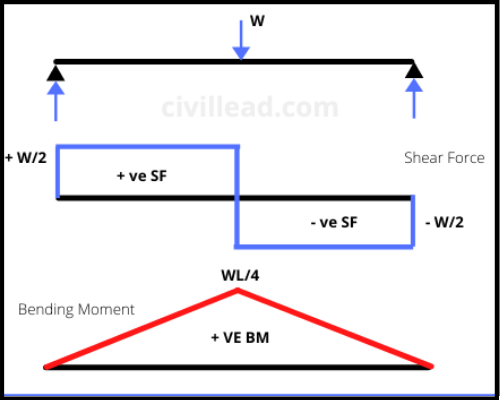
What Is Shear Force and Bending Moment? - Civil Lead
Shear and Moment Diagrams - S.B.A. Invent

How to use shear force and bending moment diagrams? : r ...

Shear and moment diagram part 4 - Mo Civil Engineering
How to Draw Shear Force & Bending Moment Diagram | Simply ...
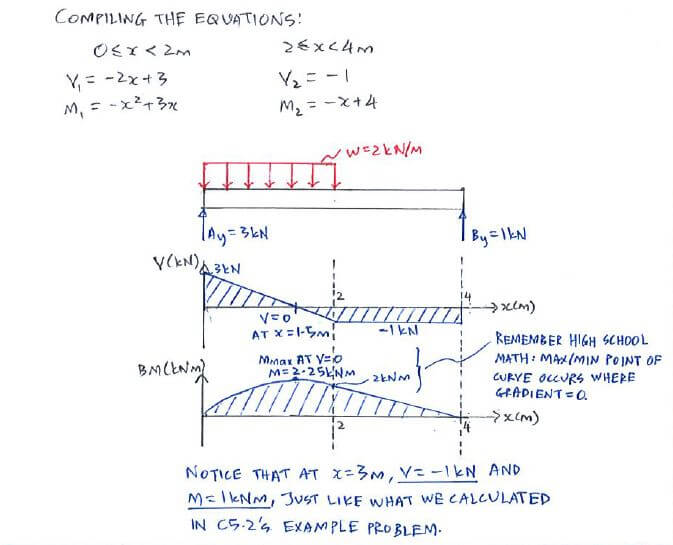
Example - Equation approach | C5.3 Shear Force and Bending ...

Drawing Shear and Moment Diagrams for Beam
The Ultimate Guide to Shear and Moment Diagrams ...
Shear Force And Bending diagrams - Roy Mech
DE-12: Lesson 19. SOLVED EXAMPLES BASED ON SHEAR FORCE AND ...
Can you draw the shear force and bending moment diagrams of ...

File:Shear Moment Diagram.svg - Wikimedia Commons
Solved] EXAMPLE 3-2 Derive the loading, shear-force, and ...
The Ultimate Guide to Shear and Moment Diagrams ...
Shear Force and Bending Moment diagram for Simple supported beam

Draw the shear and moment diagram for the beam and loading ...

Shear Force and Bending Moment Diagrams: This website is ...
0 Response to "40 shear and moment diagram examples"
Post a Comment