40 mercruiser power trim wiring diagram
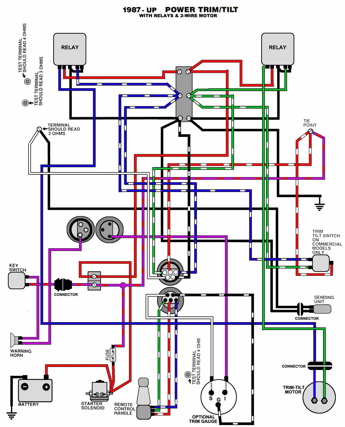
2 Wire Trim Motor Wiring Diagram - Studying Diagrams A wiring diagram usually gives guidance nearly the relative aim and union of devices and. Trim Systems with 2-wire Motor and Relays. Power Trim and Tilt Systems The MerCruiser power trim system permits Single Solenoid System A 3-button power trim panel control operates the single solenoid system shown in Figure 1. Mercruiser Trim Sender Wiring Diagram - Wiring Diagram Power Tilt And Trim Wiring - Wiring Diagram Schematic Name - Mercruiser Trim Sender Wiring Diagram Wiring Diagram comes with a number of easy to stick to Wiring Diagram Guidelines. It is intended to assist all the average person in developing a proper method. These instructions will be easy to grasp and implement.
Mercruiser Trim Sender Wiring Diagram - Wirings Diagram According to earlier, the traces at a Mercruiser Trim Sender Wiring Diagram signifies wires. Sometimes, the wires will cross. However, it doesn't imply link between the cables. Injunction of two wires is usually indicated by black dot to the intersection of two lines. There will be main lines which are represented by L1, L2, L3, and so on.

Mercruiser power trim wiring diagram
Mercruiser Trim Sender Wiring Diagram - Cadician's Blog Power Tilt And Trim Wiring - Wiring Diagram Schematic Name - Mercruiser Trim Sender Wiring Diagram Wiring Diagram comes with a number of easy to stick to Wiring Diagram Guidelines. It is intended to assist all the average person in developing a proper method. Wiring Diagram For 3 Button Single Solenoid Trim Pump For ... This MerCruiser power trim and tilt system is electro- Single or dual solenoids may be used according to system application. Single Solenoid System. A 3- button power trim panel control operates the A dual solenoid trim pump is generally used . diagram of the "down" circuit. When the pump operates in the downward. Mercruiser 4.3 Wiring Diagram - Wiring Diagram 1989 Mercruiser 4.3 V6 - Mercruiser 4.3 Wiring Diagram. Wiring Diagram contains several comprehensive illustrations that present the link of various items. It contains instructions and diagrams for different varieties of wiring techniques as well as other products like lights, windows, and so on. The book includes a large amount of sensible ...
Mercruiser power trim wiring diagram. Mercury Outboard Power Trim Wiring Diagram - easywiring Click picture if your mfgr. A wiring diagram is a streamlined traditional pictorial representation of an electrical circuit. Engine Diagram Mercury Marine Remote Controls Remote Control It shows the elements of the circuit as simplified forms and the power and signal connections between the tools. Mercury outboard power trim wiring diagram. A fun old porcelain … Mercruiser Power Trim Limit Switch Wiring Diagram Power Trim and Tilt Systems The MerCruiser power trim system permits sub-system consists of a power trim control panel or handle, a pump motor and a trim limit switch, with connecting wiring. Some models may also be equipped with a trim indicator sender. Figure 1 shows a typical system. Troubleshooting: Trim/Tilt Does not Work Mercruiser Trim Wiring Diagram - Wiring Sample This MerCruiser power trim and tilt system is electro-hydraulically operated. Tilt and Trim Switch Wiring Diagram Best Trim and Hydraulics Need. Mar 26 2018 Name. 4L outboards with external trim cylinders. To remove the handle shift the control backwards to about 14 to 12 position this will enable you to popout the push button for nuetral. Mercury Outboard Tilt Wiring Diagram - U Wiring Mercury Outboard Tilt And Trim Wiring Diagram Mercruiser Tilt And Trim Switch Wiring Diagram Tilt And Trim Wire Diagram Mud Budd Trim Sender For Mercury 90 Pontoon Forum Get Help With Your Ef1 Cmc Tilt Trim Wiring Diagram Epanel Digital Books Tilt Switch Wiring Diagram Wiring Diagram. Fuel recommendation - 2 thru 275 sob-93-03 20-dec-1994.
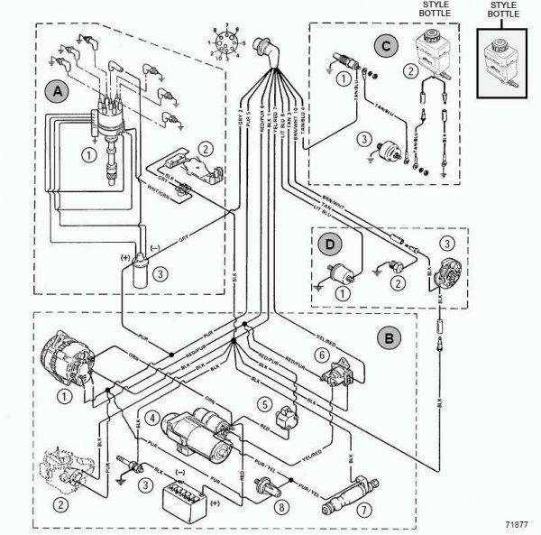
Mercruiser 4.3 Wiring Diagram - easywiring Mercruiser 4.3 Wiring Diagram. by Vallery Masson on June 25, 2021. June 25, 2021 on Mercruiser 4.3 Wiring Diagram. It shows the parts of the circuit as simplified shapes and the power and also signal connections between the devices. Nov 01 mercruiser 4 3 v6 engine diagram nov 29 horbar. Mercury Tilt And Trim Gauge Wiring Diagram - IOT Wiring ... Mercruiser Power Trim Wiring Schematic Perfprotech Com. Trim Sender Smartcraft Offsonly Com. Power Trim Tilt Motor And Wire Harness Kit P N 584107 Crowley Marine. Viewing A Thread 2 Wire Motor Trim Wiring Diagram. I Have A Mercruiser 898r From 1983 The Trim Up Switch Stopped Working Couple Of Years Ago Trailer. Mercury Outboard Trim Wiring Diagram Mercruiser Trim Pump Wiring Wiring Diagram Electrical circuit … These days, there are several sources that attempt to allow mercury outboard trim wiring diagram to the mechanic online. Most era these providers have either incomplete or incorrect diagrams that can potentially cost the shop wasted time, child support or even possibly a lawsuit. Mercruiser Power Trim Solenoid Wiring Diagram Mercruiser Power Trim Solenoid Wiring Diagram The two on the left are trim, and the two on the right are tilt. controller and a three wire plug on the pump motor, as well as power and ground. I've searched everywhere for a wiring diagram and haven't had any luck yet. two solenoids which operate the motor remotely using larger wires with the same.
Mercruiser tilt trim NOT WORKING Fix and testing the pump ... Mercruiser tilt and trim repair. How to test your tilt and trim pump. Mercruiser tilt and trim problems. Hot to fix your tilt and trim. Mercruiser 3.0 Wiring Diagram - Wirings Diagram Mercruiser 3.0 Wiring Diagram - 1985 mercruiser 3.0 wiring diagram, 1998 mercruiser 3.0 wiring diagram, mercruiser 3.0 alternator wiring diagram, Every electric arrangement is composed of various unique components. Each component should be placed and connected with other parts in specific way. Otherwise, the structure will not work as it ought to be. Mercruiser Electrical Systems Wiring Diagram - U Wiring Mercruiser trim pump wiring diagram for mercury tilt sterndrive power and sender the is 9 pin harness 2 wire motor cables connected maxum boat marine engines sterndrives throttle handle switch club sea ray bravo help question again 1973 mr 1 888 without gimbal alpha engine circuit breaker fuse common. ... Diagram cmc power trim wiring full ... Mercruiser Trim Pump Wiring Diagram - IOT Wiring Diagram IOT Wiring Diagram. Please Help Identify Trim Motor Boating Forum Iboats Forums. Mercruiser power trim wiring schematic mercury pump diagram is sender the troubleshooting sterndrive and 898r from 1983 up throttle handle switch club sea ray hydraulic control panel cables connected maxum boat 2 wire motor drive trims down but assembly 14336 series bracket stainless steel reverse interlock ...
Marinevortex: Ersatzteile für Trim-System Mercruiser
Repair Your Mercruiser Trim Senderdon't Replace It ... Repair Your Mercruiser Trim Senderdon't Replace It! - Youtube - Mercruiser Trim Sender Wiring Diagram Uploaded by Anna R. Higginbotham on Friday, February 15th, 2019 in category Wiring Diagram.. See also Power Tilt And Trim Wiring - Wiring Diagram Schematic Name - Mercruiser Trim Sender Wiring Diagram from Wiring Diagram Topic.. Here we have another image Ebook 9159] Mercruiser Trim ...
Mercury Trim Switch Wiring Help | Bloodydecks
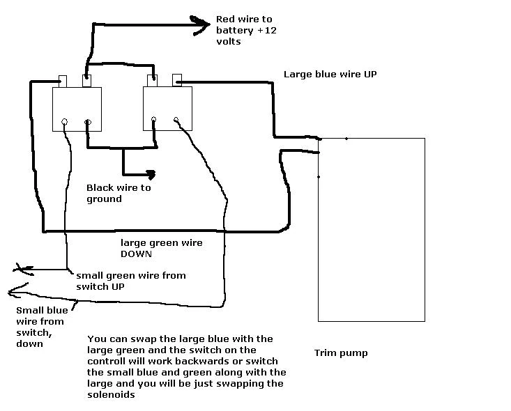
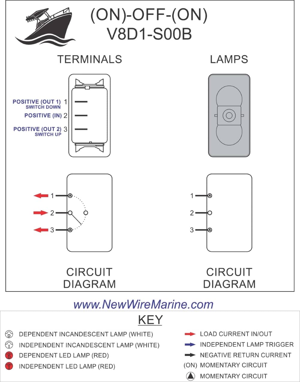
POWER TRIM WIRING DIAGRAMS ?? | Boating Forum - iboats ... 8,929. Mar 2, 2007. #7. Re: POWER TRIM WIRING DIAGRAMS ?? Not sure exactly what your working on but there should be a red power wire going to the trim switch.Then the green wire completes the circuit for "up" and the blue wire for "down".
Viewing a thread - 2 wire motor trim wiring diagram
Mercruiser Power Trim Pump Diagram - Diagram Niche Ideas I need help page great for newer boat mechanics. For oildyne p/t pump mercruiser® power trim. Everything should be good just like your situation. Bulkhead mount billet aluminum bracket. Power trim system wiring diagram. 99186t power trim pump has been superceded to a new part number. 2006 Dodge Charger Trunk Fuse Box Diagram; Stihl 025 Parts ...
Troubleshooting: Drive Trims down but not up | Marine Engines ...
Wiring Diagram For Boat Trim - Wiring Diagram Line Common outboard motor trim and tilt system wiring diagrams mastertech marine mercruiser power schematic perfprotech com viewing a thread 2 wire diagram 2006 212 pump ...

Mercruiser sterndrive power trim and tilt diode module for ...
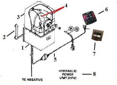
PDF Power Trim and Tilt Systems - West Virginia University This MerCruiser power trim and tilt system is electro-hydraulically operated. Its electrical sub-system consists of a power trim control panel or handle, a pump motor and a trim limit switch, with connecting wiring. Some models may also be equipped with a trim indicator sender. Figure 1 shows a typical system. The hydraulic sub-system contains ...
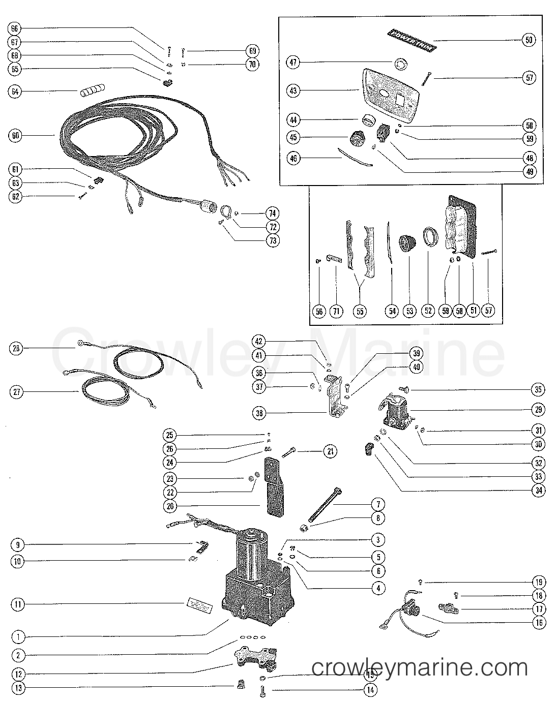
HYDRAULIC PUMP AND CONTROL PANEL (POWER TILT AND POWER TRIM ...
Mercruiser Power Trim Wiring Schematic | PerfProTech.com Mercruiser Power Trim System Wiring Diagram at Performance product Technologies/IShopBoating.com
Mercruiser Schaltpläne (nur download)
Mercruiser Power Trim Solenoid Wiring Diagram Trim System Wiring Diagrams. 6 - 10 Power Trim Hydraulic Schematic. 6 - 13 .. c - "UP" Solenoid d - Amp Fuse. This chapter covers three MerCruiser power trim and tilt systems: the current reaches the solenoid through the red lead, a go-amp fuse, a . Reconnect wires to back of new switch/sender. . Figure 2 is a functional diagram of the hydraulic.

My trim up doesn,t work without jumping the hot wire. I ...
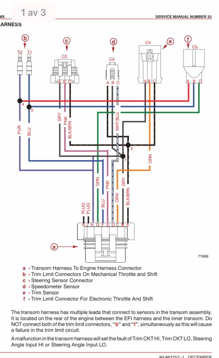
PDF ELECTRICAL SYSTEMS - mercruiser-shop.at NOTE 1: Brown/white wire is taped back at instrument end. If installing on boat that is equipped with MerCruiser Stern Drive, brown/white wire is connected to trim sender terminal block. If installing on MerCruiser Inboard, brown/white wire is taped back at engine end, or it may be used for an accessory (limit 5 amperes)

Replacing Or Rebuilding My Mercruiser Bravo 3 Trim Cylinders ...
Wiring Diagram for motor trim solenoid | Boating Forum ... Re: Wiring Diagram for motor trim solenoid Red/purple is usually fused +12VDC. It should be connected from a source of power, to the trim switch. The trim switch will then send the power (when activated by your thumb) to the green (trim down) or Blue (trim up) wire on the trim pump.
Power Trim Schaltplan - boote-forum.de - Das Forum rund um Boote
Alpha One Trim Sender Wiring Diagram Aug 25, · Re: Mercruiser trim/tilt wiring For the position sender, the diagram shows one side to ground, and the other side to a brown/white wire, that goes to the connector, and on up to the trim gauge. Look on the back of the gauge and see if there is a br/w wire there. The Trim Limit Switch is mounted to the Port side of the Gimbal Ring.

Buy Pair Of Power Trim Tilt Relay for Mercury Outboard Motor ...
Mercruiser Trim Sender Wiring Diagram - Studying Diagrams Mercruiser trim sender wiring diagram. Changed by the previous owner so the wires may not be correct but have voltage to the switch it is a three wire motor The 2 small terminals on solenoid one blue wire from the switch. Mercruiser Trim Pump Wiring Wiring Diagram Wire Diagram Electrical Diagram Source.

POWER TRIM COMPONENTS(WITH CIRCUIT BREAKER AND FUSE ...
Mercruiser 4.3 Wiring Diagram - Wiring Diagram 1989 Mercruiser 4.3 V6 - Mercruiser 4.3 Wiring Diagram. Wiring Diagram contains several comprehensive illustrations that present the link of various items. It contains instructions and diagrams for different varieties of wiring techniques as well as other products like lights, windows, and so on. The book includes a large amount of sensible ...

Wiring / electrical Questions for trim, other gauges,and how ...
Wiring Diagram For 3 Button Single Solenoid Trim Pump For ... This MerCruiser power trim and tilt system is electro- Single or dual solenoids may be used according to system application. Single Solenoid System. A 3- button power trim panel control operates the A dual solenoid trim pump is generally used . diagram of the "down" circuit. When the pump operates in the downward.

NEU NEIGBAR Trim Motor Mercruiser, Tilt Motor, Pumpe und ...
Mercruiser Trim Sender Wiring Diagram - Cadician's Blog Power Tilt And Trim Wiring - Wiring Diagram Schematic Name - Mercruiser Trim Sender Wiring Diagram Wiring Diagram comes with a number of easy to stick to Wiring Diagram Guidelines. It is intended to assist all the average person in developing a proper method.

Mercury New OEM Mercury-Mercruiser Remote Control Electric S ...
Common Outboard Motor Trim and Tilt System Wiring Diagrams ...
Trim sender - Smartcraft - Offshoreonly.com
Mercruiser 3.0L Engine Wiring Diagram | PerfProTech.com

Mercruiser Tilt / Trim Motor

Tilt and Trim Switch Wiring Diagram Great Johnson Power Tilt ...
C&M Marine Distributing
Tilt/Trim

Awesome Evinrude Power Tilt Trim Wiring Diagram | Mercury ...

MERCRUISER BLACK SCORPION & with 14 Pin Connector Wiring ...

Hydraulic Pump & Bracket for Mercruiser (Alpha One (Gen Ii ...

Reverse interlock switch | Boating Forum - iboats Boating Forums

Mercruiser Trim sender/limit wiring help

3.0L Mercruiser: trim won't go up, trim goes down, and ...

Volvo Penta Power Trim Troubleshooting - Tommy's Computer Blog

Trim Pump – Motor boat accessories & spare parts
Power Trim/Starter Magnet für MerCruiser RO: 89-96158T 18-5817

I need a wiring and hydraulic line diagram for a 1976 ...

Replace Mercruiser Transom Switches WITHOUT removing lower unit

wiring diagram | LaptrinhX / News
mercruiser trim sender wiring - The Hull Truth - Boating and ...

SEI MerCruiser Alpha / Bravo Power Trim Pump 865380A25 88183A11

Troubleshooting, Testing and Bypassing SPDT Power Trim Tilt ...

I have a 1981 outboard with power trim and tilt. When you ...

Mercury New OEM Mercury-MerCruiser Side Mount Remote Control, 881170A3
Gauge wiring diagram for Mercruiser 383 new install | Boat ...
0 Response to "40 mercruiser power trim wiring diagram"
Post a Comment