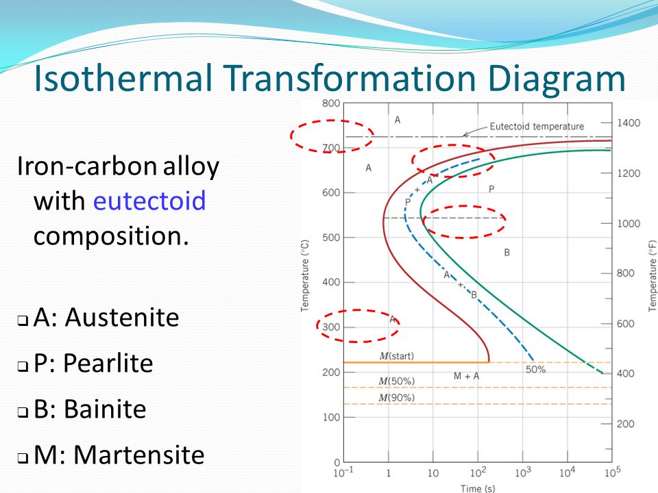
38 isothermal transformation diagram for an iron–carbon alloy
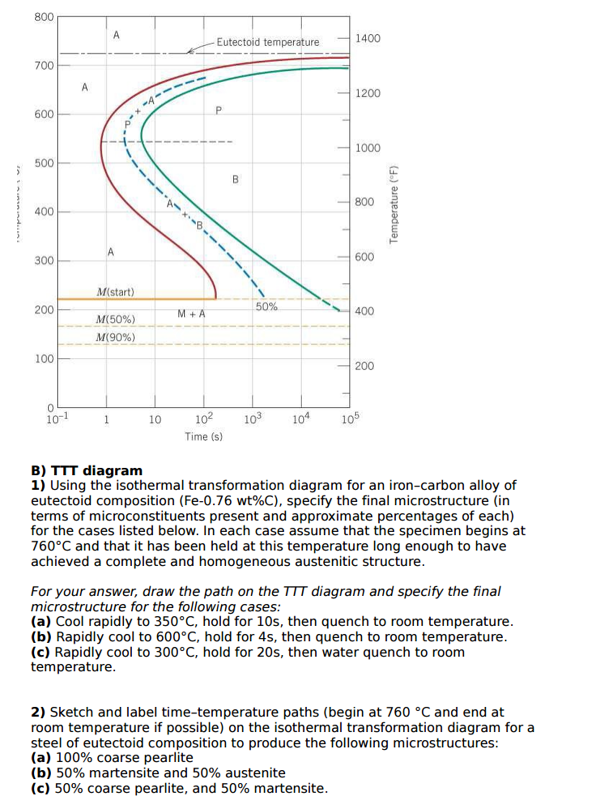
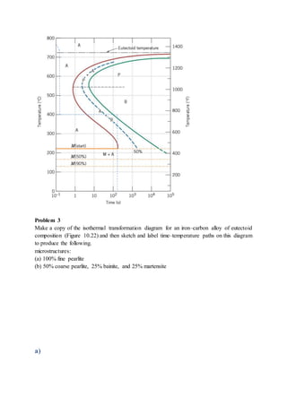
PDF TTT & CCT Diagram Part 2 Lect-6 - University of Technology ... Using the isothermal transformation diagram for an iron—carbon alloy of eutectoid composition (Figure 10.22), specify the nature of the final microstmcture (in tenns of microconstituents present and approximate percentages of each) of a small specimen that has been subjected to the following time—temperature treatments. Make a copy of the isothermal transformation diagram for a ... Make a copy of the isothermal transformation diagram for a 0.45 wt% C iron-carbon alloy (Figure 10.40), and then sketch and label on this diagram the time-temperature paths to produce the following microstructures: (a) 42% proeutectoid ferrite and 58% coarse pearlite. (b) 50% fine pearlite and 50% bainite (c) 100% martensite (d) 50% ...
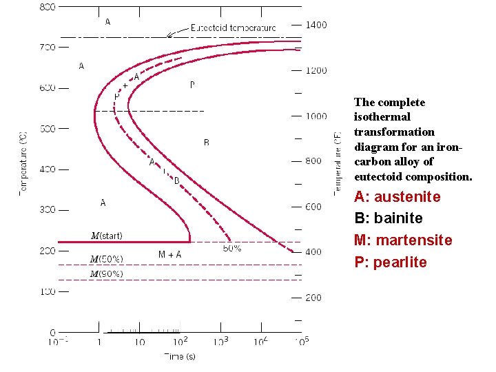
Iron Carbon Ttt Diagram - wiringall.com Iron Carbon Ttt Diagram. TTT diagram is a plot of temperature versus the logarithm of time for a steel alloy of The complete isothermal transformation diagram for an iron-carbon alloy. Imagine, for example, some pure iron that was kept at a temperature of oC ( .. Here is the "official" isothermal TTT diagram for eutectoid carbon steel.
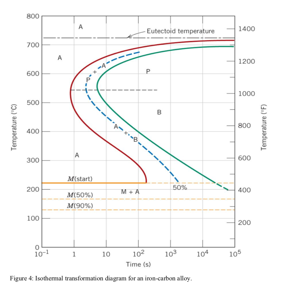
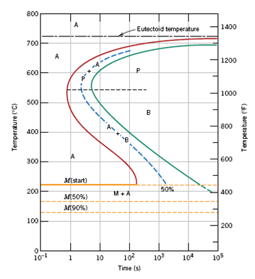
Isothermal transformation diagram for an iron–carbon alloy
PDF CHAPTERS 9 & 10 PHASE DIAGRAMS and TRANSFORMATIONS IN ... 10.18 Below is shown an isothermal transformation diagram for a 0.45 wt% C iron-carbon alloy, with time-temperature paths that will produce (a) 42% proeutectoid ferrite and 58% coarse pearlite; (b) 50% fine pearlite and 50% bainite; (c) 100% martensite; and (d) 50% martensite and 50% austenite. Phase Transformation in Metals (Chapter 10).pdf - Phase ... Sample Question 1 Sketch and label time - temperature paths on this diagram to produce the following microstructures: (a) 100% coarse pearlite (b) 50% martensite and 50% austenite (c) 50% coarse pearlite, 25% bainite, and 25% martensite 38 Figure 10.22 The complete isothermal transformation diagram for an iron-carbon alloy of eutectoid ... Solved 1. Problem 1 Attached is the isothermal | Chegg.com Problem 1 Attached is the isothermal transformation diagram for an iron-carbon alloy of eutectoid composition: A, austenite; B, bainite; M, martensite; P, pearlite. Sketch and label time- temperature paths on this diagram to produce the following microstructures: a) 100% coarse pearlite b) 50% martensite and 50% austenite c) 50% coarse pearlite ...
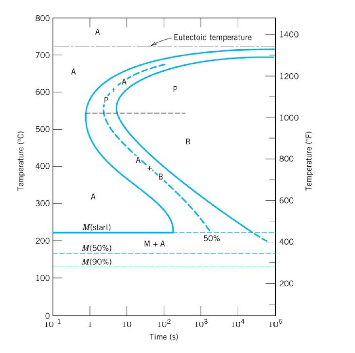
Isothermal transformation diagram for an iron–carbon alloy. Using the isothermal transformation diagram for an iron ... Using the isothermal transformation diagram for an iron-carbon alloy of eutectoid composition, specify the nature of the final microstructure (in terms of microconstituents present and approximate percentages of each) of a small specimen that has been subjected to the following time-temperature treatments. Solved Using the isothermal transformation diagram for an ... Using the isothermal transformation diagram for an iron-carbon alloy of eutectoid composition (Figure 10.23), specify the nature of the final microstructure (in terms of microconstituents presentand approximate percentages of each) of a small specimen that has been subjected to the following time -temperature treatments. Assignment 2 solutions - SlideShare Problem 2 Using the isothermal transformation diagram for an iron-carbon alloy of eutectoid composition (Figure 10.22), specify the nature of the final microstructure (in terms of microconstituents present and approximate percentages of each) of a small specimen that has been subjected to the following time- temperature treatments. PDF Isothermal Transformation Diagrams 10.18 Using the isothermal transformation diagram for an iron-carbon alloy of eutectoid composition (Figure 10.22), specify the nature of the final microstructure (in terms of microconstituents present and approximate percentages of each) of a small specimen that has been subjected to the following time-temperature treatments.
PDF Time-Temperature-Transformation (TTT) Curves Using the isothermal transformation diagram for an iron-carbon alloy of eutectoid composition, specify the nature of the final microstructure of a small specimen that has been subjected to the following time-temperature treatments. EOF PDF Experiment #7 Phase Transformations & Hardenability of ... Isothermal transformation diagram for an iron-carbon alloy of eutectoid composition, including austenite-to-pearlite (A-P) and austenite-to-bainite (A-B) transformations. "Nose" of T-T-T curve between pearlite and bainite transformations means bainite cannot be Material Science Flashcards | Quizlet Below is shown the isothermal transformation diagram for a 0.45 wt% C iron-carbon alloy. List the microconstituent(s) present for the heat treatment labeled (a) on this diagram. It is not necessary to state the proportion(s) of the microconstituents.
Iron Carbon Ttt Diagram - schematron.org TTT diagram is a plot of temperature versus the logarithm of time for a steel alloy of The complete isothermal transformation diagram for an iron-carbon alloy.C metastable equilibrium diagram and TTT diagrams for plain carbon hypoeutectoid, eutectoid and hypereutectoid steels M S (a) Fe-Fe 3 C metastable phase diagram (b) TTT diagram for ... PDF 10.13 The complete isothermal transformation diagram for ... Isothermal transformation diagram for an alloy steel (type 4340): A, austenite; B, bainite: P, pearlite; M, martensite; F, proeutectoid ferrite. [Adapted from H. Boyer (Editor), Atlas of Isothermal Transformation and Cooling Transformation Diagrams, American Society for Metals, 1977, p. 181.1 800 - 600 500 400 300 200 100 Eutectoid temperature ... TTT Diagram Basic - TTT diagram for steel, eutectoid steel Time-Temperature-Transformation (TTT) diagram or S-curve refers to only one steel of a particular composition at a time, which applies to all carbon steels.This diagram is also called as C-curve isothermal (decomposition of austenite) diagram and Bain's curve.The effect of time-temperature on the microstructure changes of steel can be shown by the TTT diagram. Solved 1. Problem 1 Attached is the isothermal | Chegg.com Problem 1 Attached is the isothermal transformation diagram for an iron-carbon alloy of eutectoid composition: A, austenite; B, bainite; M, martensite; P, pearlite. Sketch and label time- temperature paths on this diagram to produce the following microstructures: a) 100% coarse pearlite b) 50% martensite and 50% austenite c) 50% coarse pearlite ...
Module 5 Metallic Materials http www tntech ...
Phase Transformation in Metals (Chapter 10).pdf - Phase ... Sample Question 1 Sketch and label time - temperature paths on this diagram to produce the following microstructures: (a) 100% coarse pearlite (b) 50% martensite and 50% austenite (c) 50% coarse pearlite, 25% bainite, and 25% martensite 38 Figure 10.22 The complete isothermal transformation diagram for an iron-carbon alloy of eutectoid ...
CHAPTER 10
PDF CHAPTERS 9 & 10 PHASE DIAGRAMS and TRANSFORMATIONS IN ... 10.18 Below is shown an isothermal transformation diagram for a 0.45 wt% C iron-carbon alloy, with time-temperature paths that will produce (a) 42% proeutectoid ferrite and 58% coarse pearlite; (b) 50% fine pearlite and 50% bainite; (c) 100% martensite; and (d) 50% martensite and 50% austenite.
TTT Phase transformation | Physics Forums
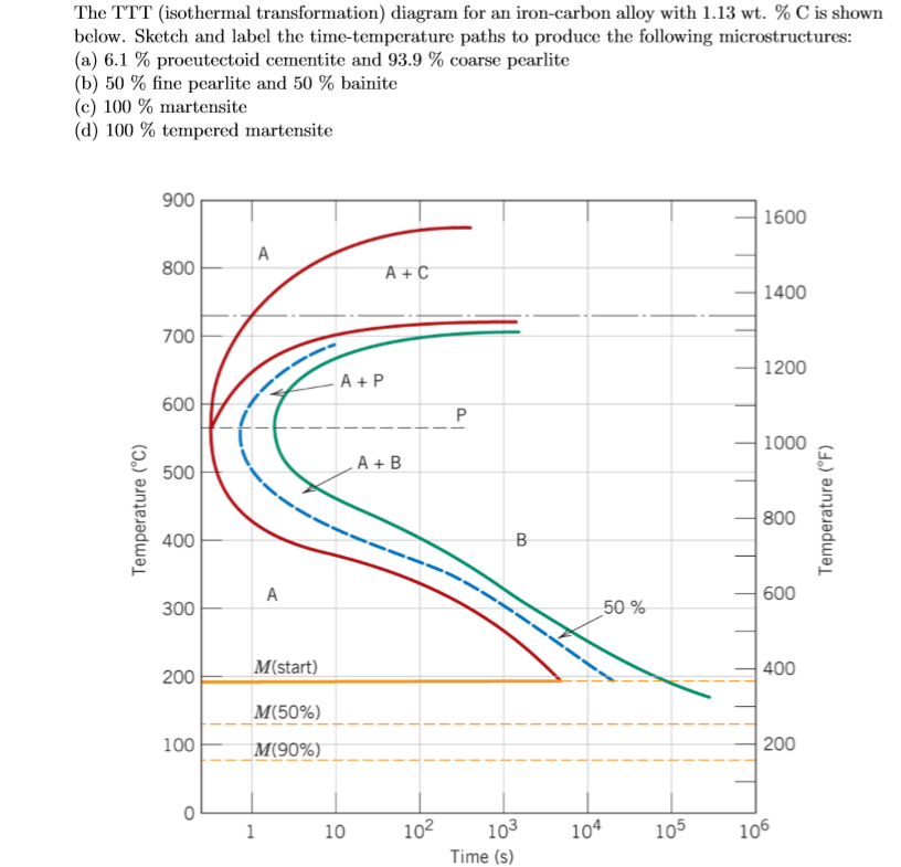
Solved The TTT (isothermal transformation) diagram for an ...
Analysis of Carbon–iron (Fe–Fe3C) Phase Diagram 1. Experimental
![Solved] On the basis of accompanying isothermal ...](https://s3.amazonaws.com/si.question.images/image/images16/1403-P-M-P-A-S(2066).png)
Solved] On the basis of accompanying isothermal ...

An isothermal transformation diagram for a medium carbon ...
Metals | Free Full-Text | Effects of Chemical Composition and ...
Teach Yourself Phase Diagrams and Phase Transformations

OneClass: Using the supplied isothermal transformation ...

Using the isothermal transformation diagram for an iron ...
Phase Transformation
Phase Transformations in Metals - ppt download
Solved Qu. 8 Using the isothermal transformation diagram for ...
![EM_UNIT_4_PPT [2015 Pattern] Pages 51-100 - Flip PDF Download ...](https://online.fliphtml5.com/cldig/vcmy/files/thumb/51.jpg?1583833062)
EM_UNIT_4_PPT [2015 Pattern] Pages 51-100 - Flip PDF Download ...
Solved Using the isothermal transformation diagram for an ...
Solved Using the isothermal transformation diagram for an ...
Solved Using the isothermal transformation diagram for an ...

An isothermal transformation diagram for a typical (3.5%C ...
Time- Temperature- Transformation Diagram (Or)
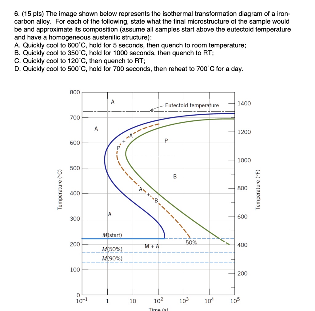
SOLVED:6. (15 pts) The image shown below represents the ...

TTT Diagram Basic - TTT diagram for steel, eutectoid steel
Chap 10 Solns

Assignment 3, 2020 fixed-Materials - Assignment 3 , 2020 Make ...

Assignment 4 (1).docx - CHG 4305 Assignment Total 100 points ...
Chapter 10. Phase Transformations in Metals

Using the isothermal transformation diagram for an iron ...

Material Science Flashcards | Quizlet

Using the isothermal transformation diagram for an iron ...
chapt 10 solutions

TTT Diagram Basic - TTT diagram for steel, eutectoid steel
Assignment 2 solutions

Isothermal transformation diagram - Wikipedia
Isothermal Transformation Diagrams
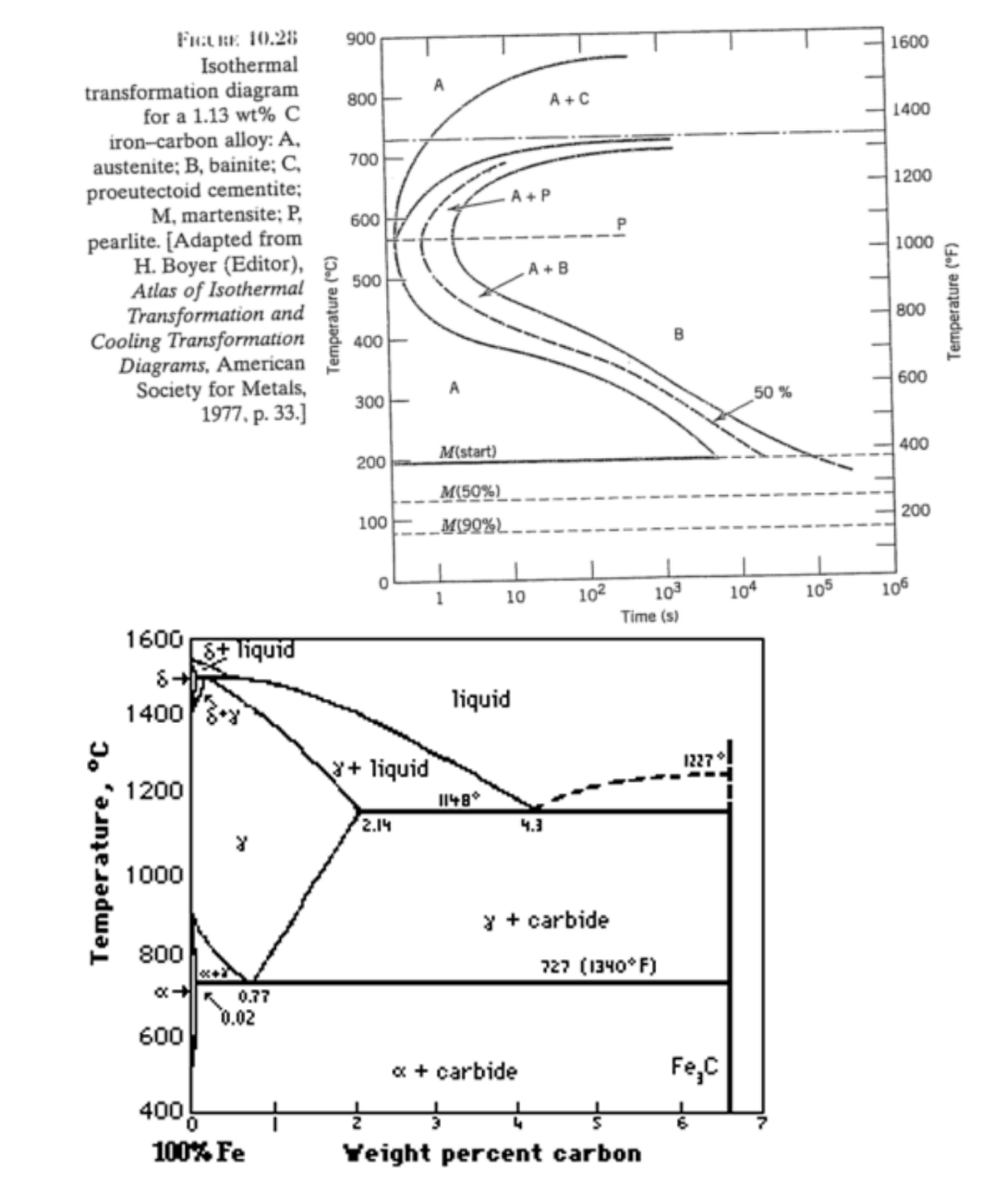
Answered: FuLRE 10.28 Isothermal 900 1600… | bartleby

Isothermal Transformation Behavior and Microstructural ...

Problem 4 The TTT (isothermal transformation) diagram ...

Assignment 2 solutions
0 Response to "38 isothermal transformation diagram for an iron–carbon alloy"
Post a Comment