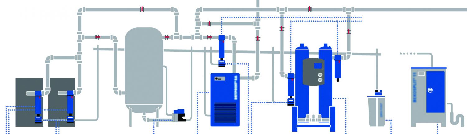
36 compressed air system piping diagram
Guide to Compressed Air Piping Systems | Quincy Compressor The purpose of compressed air piping systems is simple: to deliver compressed air to where it is needed. However, designing a compressed air system is more difficult than you might imagine — the compressed air has to be delivered with sufficient volume, good enough quality and enough pressure to power the components that require compressed air. PDF Distribution PiPing - Compressed Air Challenge Best Practices and Tips for Compressed Air Piping Systems A brief synopsis of "Section 3, Distribution System" from Best Practices for Compressed Air Systems follows. This 325-page book is available at our bookstore. Pressure losses due to inadequate piping will result in increased energy costs and variations
Air Compressor Piping Diagrams and Tips - Best of Machinery Feb 01, 2022 · When you attach a compressor to an end-user device through a pipe, you have created your very own air compressor piping diagram. This is all very simple when we speak about it in such terms, but it can be more complicated to create. To create your own air compressor piping diagram, you need to know your project’s requirements.

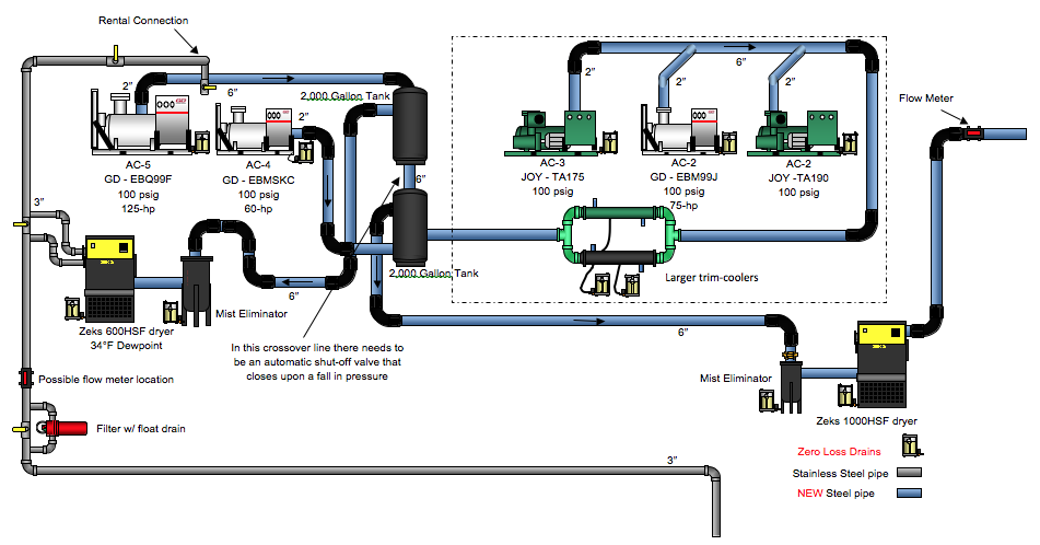
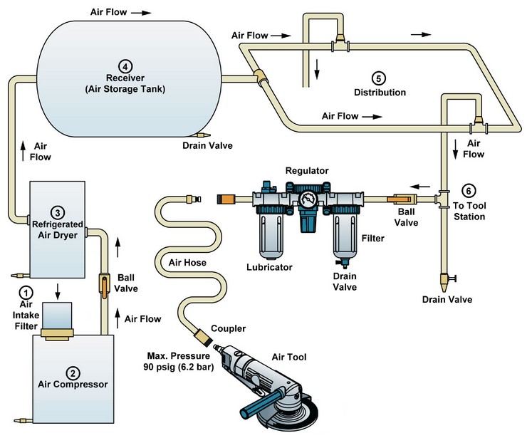
Compressed air system piping diagram
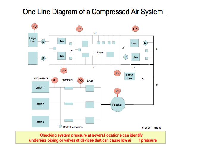
PDF How to know what size piping your Compressed Air System needs the overall air system. Steps to figuring what size piping your compressed air system needs: 1. Determine your air compressor's maximum CFM. 2. Draw a piping schematic and show all pipe fittings, valves, etc. 3. Measure and write the corresponding lengths of pipe on your schematic, then total the length of all straight pipes needed and note ... PDF Introduction INTRODUCTION TO BEST PRACTICES FOR COMPRESSED ... Best Practices for Compressed Air Systems xv SUMMARY OF KEY POINTS FROM COMPRESSED AIR CHALLENGE® TRAINING: "Fundamentals of Compressed Air Systems" and "Advanced Management of Compressed Air Systems" 1. Know what equipment you have. Develop a basic block diagram of compressors, dryers, filters, Air Compressor Piping Diagrams and Tips - Home Tool Guides The compressor specifications and parts suppliers usually provide a chart or manual to figure out the correct moisture content. Obstruction Destruction. I'm not sure who's worse, the obstruction that caused the break in your air piping, or the one who sold the system. As a tech in the field, it's been my experience that a broken air system is ...
Compressed air system piping diagram. Air Compressor Piping Diagrams and Tips From Experts ... Feb 15, 2019 · General Rules of Air Compressor Piping Diagrams. Piping is a very important component when it comes to designing and developing a successful air compressor system. As compressed air faces a risk of losing pressure across the system (pressure drop), or even contamination along its path. Compressed Air Basics - Piping - Air Compressor Works, Inc. Compressed Air Basics - Piping. February 23, 2018. Your air compressor is the heart of your air system. Most customers focus on the compressor and consider the piping as a secondary concern. However, just like a heart can fail because of clogged arteries, a compressor can fail because of improper piping. You have many different options on the ... Air Compressor Piping Diagrams And Tips | iPower Toolz Remember, the theory is quite different from practical. Even though the brochure will tell you that the basics involved in this pipework are easy, just connect an air tool with the compressor, while using a pipe. Well, the reality can be disappointing sometimes, because when you make use of those steps from the brochure, you will find that it is a little trickier than expected. How you might ask? Well let’s consider a paint-spraying machine, this heavy air-purifying tool requires ventilation and seclusion. For these reasons, you would have to keep it near an exterior wall. Other such end-use devices have similar requirements as a paint spraying machine. When the majority of your air tools require an outside wall, it creates a challenge for you, because now you have to cover a ridiculously long distance to get compressed air. But before you start working on easing your supply lines, you might want to consider working on some other important issues first. Like. Air Compressor Piping Diagrams and Tips - Tools Haunt An air compressor piping diagram is created by connecting an air compressor to any end-user tool through the use of a pipe. As simple as it may sound, creating your own piping diagram at home is rather a complicated process. Besides, you need the specific requirements of your project to come up with the correct piping.
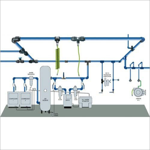
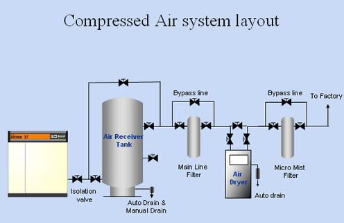
Premium Compressed Air Piping, pipes for compressed air ... RapidAir is the leader in affordable compressed air piping systems. Whether you are looking for commercial, industrial options, or are installing your first compressed air system for a client or your own garage, we make it easy to get exactly what you need, when you need it. When you need a part, you can count on us having it in stock. Design a Compressed Air System | Air System Builder | RapidAir Design Your Own Compressed Air Piping System. RapidAir's System Designer is a free 3D drawing tool that will help you easily create a compressed air piping system for your facility or workshop. Our drag-and-drop features give you complete control over your design. When you've completed the design, save your project by creating an account. Compressed Air System Schematic Diagram - SYAHME1410 Apr 15, 2020 · Figure 2 From Optimization Of Compressed Air Storage S . Volvo Service Bulletin 5 56 51 . Mellcon Hoc 7kg Cm2 100psi An Ideal Compressed Air System . Machinery Resale Offers Used Construction Equipment Solutions . A C Piping Diagram Shop Air Piping Layout Diagrams . A Hybrid Energy Storage System Using Pump Compressed Air And PDF Compressed Air System Standard Piping Diagram Compressed Air System Standard Piping Diagram Author: Department of Veterans Affairs, Office of Acquisition Logistics and Construction, Office of Construction and Facilities Management, Office of Facilities Planning, Facilities Standards Service Subject: Standard Detail Created Date: 10/26/2017 1:02:30 PM
PDF Compressed Air Piping Recommendations for Compressor ... of the air compressor. The same holds true for galvanized air compressor discharge and distribution piping. Often, due to the aggressive acidic characteristics of condensate, the life of the galvanized coating may be shorter downstream of the air compressor. Copper Piping Copper pipe is a common selection for sensitive compressed air systems and Piping and Instrumentation diagrams (P&ID) - EXAIR When it comes to drawings and diagrams to map out a process system, the piping and instrumentation diagrams (P&ID) are a great way to situate and find components. They use different symbols to represent the type of products, the layout in the system, installation, and process flow. These standard symbols are created by ANSI or ISO. Air compressor piping diagrams and tips | Learn from the ... Air piping diagram angle When working on your air compressor hose diagram, you should always avoid sharp angles. This has pretty detrimental effects on piping air to the air tool. Because these sudden sharp angles slow down the flow of air, and as a result, the pressure also drops. Let me explain it with an example. Compressed Air Piping Distribution Systems | Compressed ... Perhaps your facility recently had a compressed air system survey, conducted by an air systems services company, that resulted in a couple of major recommendations, such as: Install a new smaller compressor and new control systems on all of the units Repair the many air leaks (identified as 30% of your system capacity) These capital-intensive recommendations could involve significant process ...
DFE: Lesson 30. Compressed Air, Water And Steam
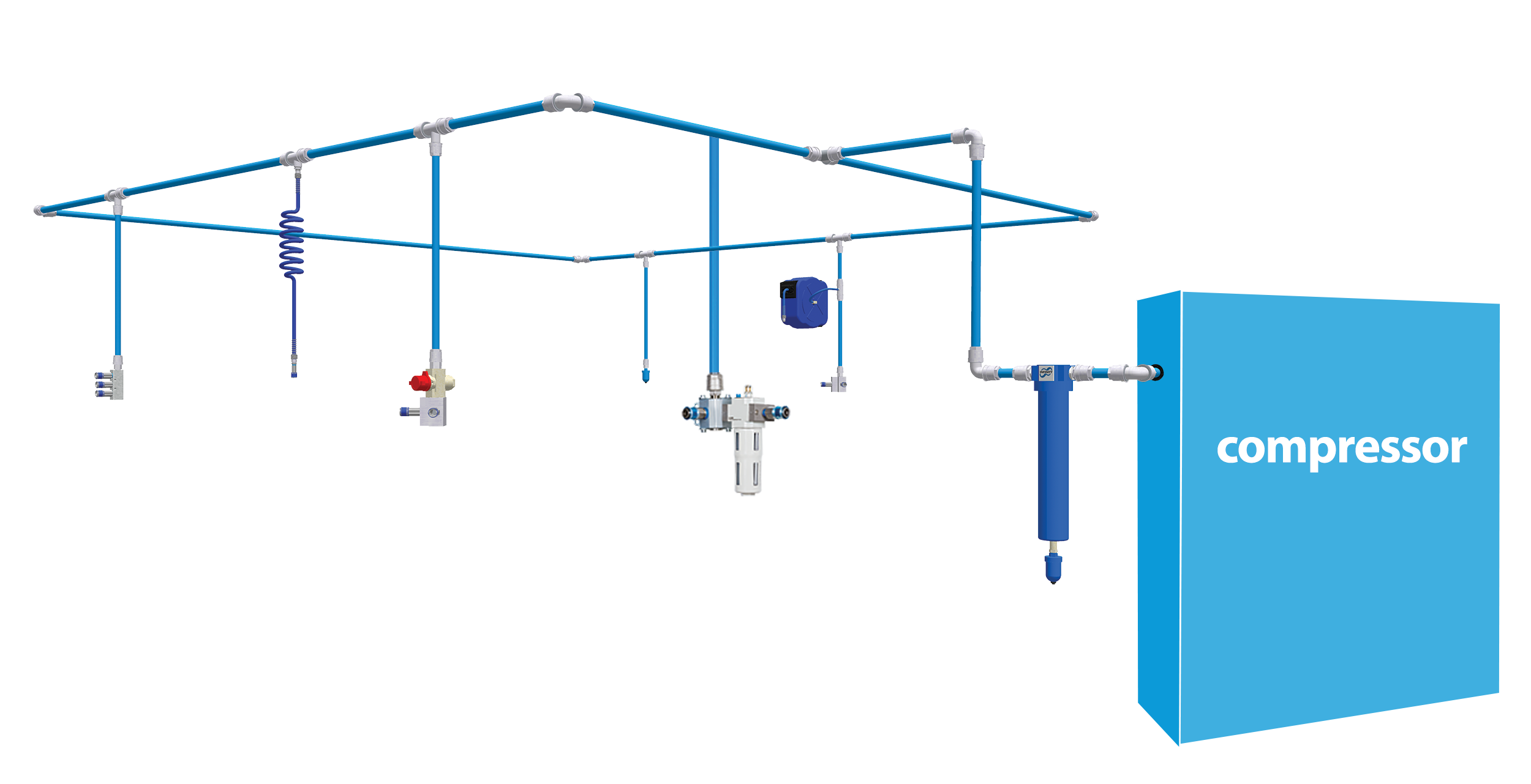
Air Piping Layout - Sharpe Manufacturing Air Piping Layout Shop Air Piping Layout Diagrams . As we all know, compressed air is a key element in everything we do in the shop. And the quality of the paint job on refinishing work is affected by the quality of the compressed air we use. The quality of our compressed air is also effected by how our air delivery lines are laid out in our shops.

Parker Legris Compressed Air Piping System, D.R Enterprises ...
Compressed Air Piping - Pressure Loss Diagrams, Imperial Units Download and print Compressed Air - Pipe Line Pressure Drop (gauge Pressure 50 psig) Compressed air pipe line pressure loss diagrams - metric units. 1 ft (foot) = 0.3048 m. 1 cfm = 1.7 m3/h = 0.028 m3/min. 1 psi = 0.069 bar = 0.070 kg/cm2.

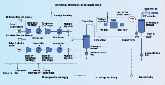
Diagram of compressed air system. 1: compressor; 2: air ...
SimplAir Compressed Air Piping | Ingersoll Rand SimplAir Compressed Air Piping. The new SimplAir piping system from Ingersoll Rand uses marine-grade aluminum pipes to efficiently distribute leak-free supplies of high-flow compressed air and other inert gasses and support vacuum systems as well. For lower cost, higher performance, easier installation, and less maintenance than systems made of ...

COMPRESSED AIR FITTINGS - Precise
Air Compressor Piping Diagrams and Tips - Home Tool Guides The compressor specifications and parts suppliers usually provide a chart or manual to figure out the correct moisture content. Obstruction Destruction. I'm not sure who's worse, the obstruction that caused the break in your air piping, or the one who sold the system. As a tech in the field, it's been my experience that a broken air system is ...

Purestream Compressed Air Piping
PDF Introduction INTRODUCTION TO BEST PRACTICES FOR COMPRESSED ... Best Practices for Compressed Air Systems xv SUMMARY OF KEY POINTS FROM COMPRESSED AIR CHALLENGE® TRAINING: "Fundamentals of Compressed Air Systems" and "Advanced Management of Compressed Air Systems" 1. Know what equipment you have. Develop a basic block diagram of compressors, dryers, filters,
TRANSAIR ALUMINIUM PIPING SOLUTIONS FOR COMPRESSED
PDF How to know what size piping your Compressed Air System needs the overall air system. Steps to figuring what size piping your compressed air system needs: 1. Determine your air compressor's maximum CFM. 2. Draw a piping schematic and show all pipe fittings, valves, etc. 3. Measure and write the corresponding lengths of pipe on your schematic, then total the length of all straight pipes needed and note ...
Design and Specification of A Compressed Air System ...

2: Pipe and instrumentation (inside compressor cabinet ...
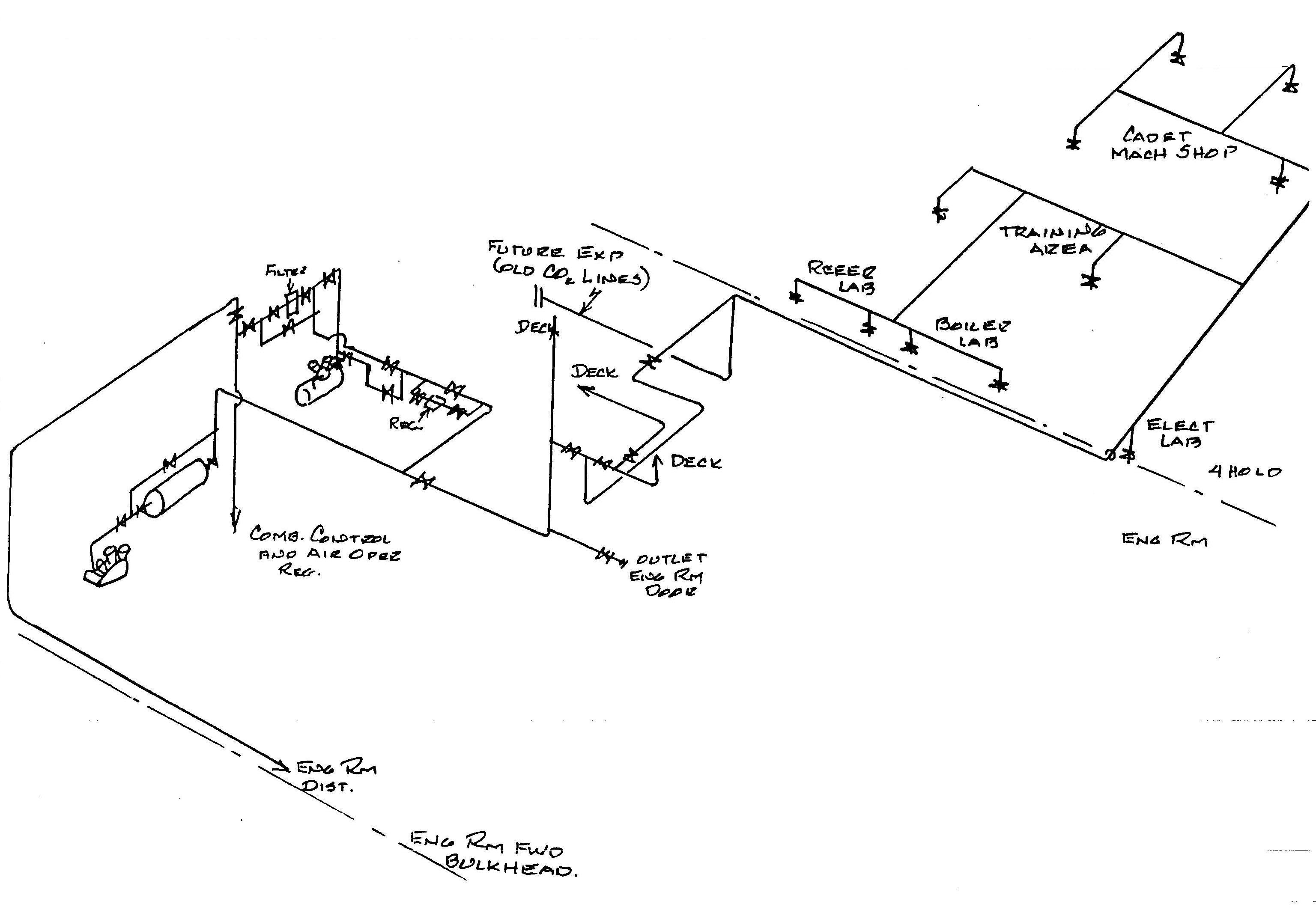
TSPS Engineering Manual

A Compressed Air Piping System Assessment - AIRpipe

Full Performance Compressed Air Pipe Systems, Compressed Air ...
Compressed Air Piping Changes Help Dairy Producer Optimize ...

7: Piping and instrumentation diagram (inside compressor ...
Air Compressor Piping Diagrams And Tips | iPower Toolz

Air compressor piping diagrams and tips | Learn from the expert
Compressed Air Piping at Wholesale Price in Delhi, Noida ...
Power Tools Dealers | Power Tools Suppliers | IR Impact ...

Diagram of compressed air systems. 1: compressor; 2: air ...

Compressed Air - Acker & Associates

What Are Compressed Air Piping Systems?
Compressed Air Piping Distribution Systems | Compressed Air ...
Compressed Air System Piping Installation & Testing Method Statement

Process Design of Instrument Air System - InstrumentationTools

Compressed Air Piping Systems - Compressor Maintenance

Vast Victory Services & Trading Sdn Bhd
Air Compressor Piping Diagrams and Tips | Tools Haunt

Qualification and Continuous Validation of a Compressed Air ...

Piping & Instrumentation Diagram of the CPTF system. In the ...

Air Piping Layout | Plumbing layout, Air compressor, Shop ...

Compressed Air Systems | Production Supply Co. LTD.
Compressed Air System | Full Aluminium Pipe Ringmain Design
Handheld Air Tools & Pneumatic Tools For 47 Years In TAIWAN ...

Shop Air Compressor Piping Diagram - Bing Images | Compressor ...

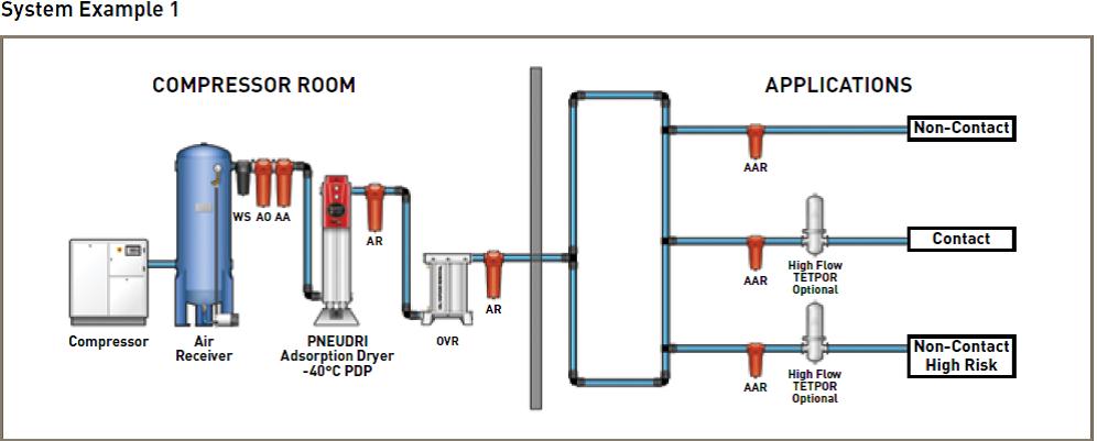
Compressed Air Piping Example - Library Pages

Compressed Air Systems (Energy Engineering)

KG Power Systems
0 Response to "36 compressed air system piping diagram"
Post a Comment