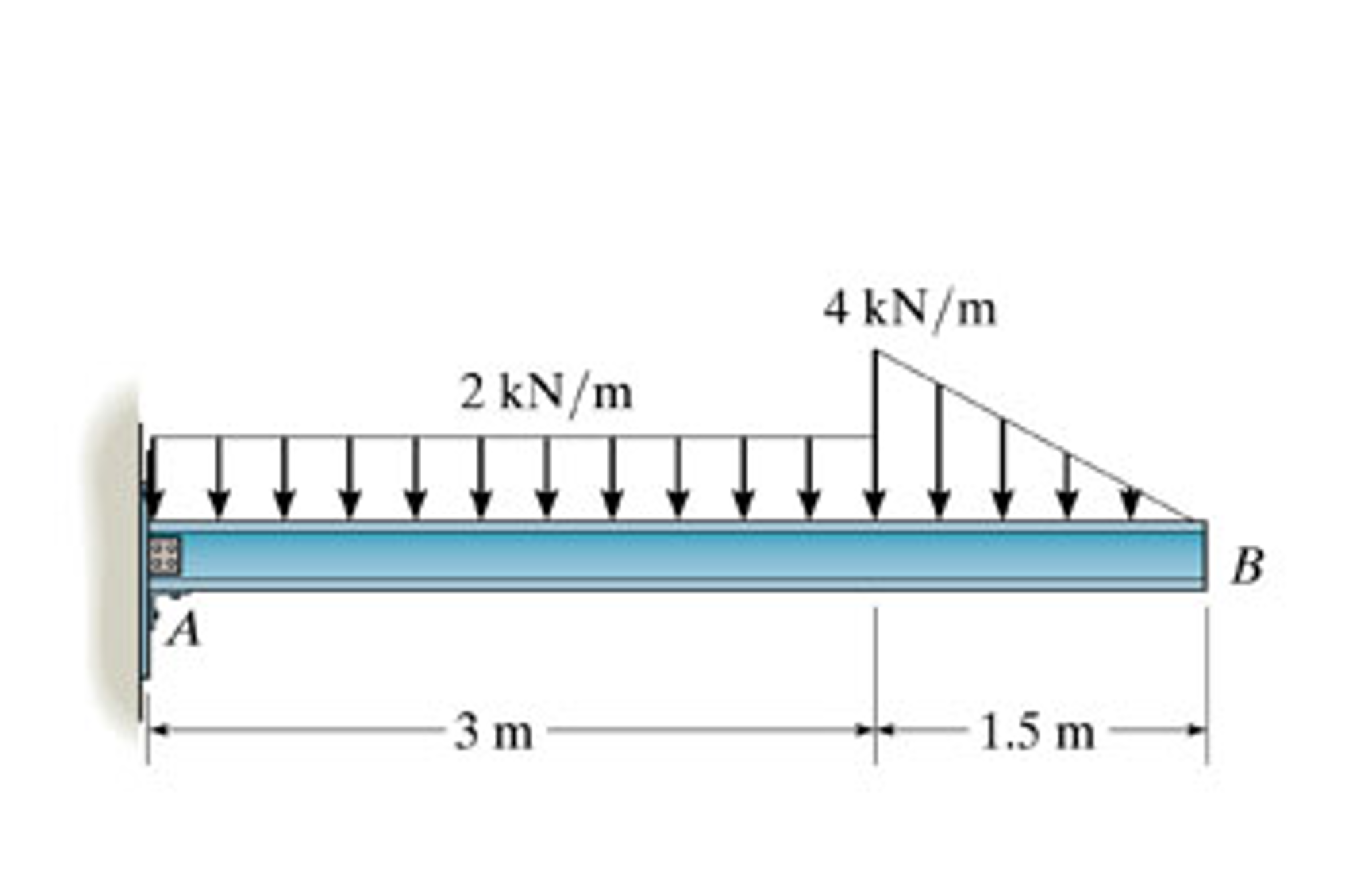
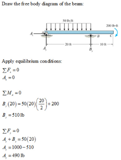
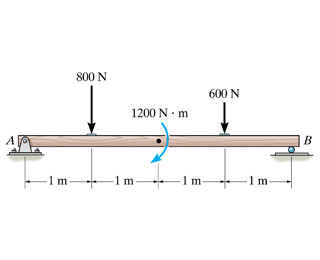
37 draw the shear diagram for the beam. follow the sign convention
Feb 04, 2022 · Feb 04, 2022 · 7.79 draw the shear diagram for the beam. Nov 24, 2016 This question can be found in Engineering Mechanics: Statics (SI edition), 13th edition, chapter 3, question 3-43. Leave a comment Cancel reply Your email address will ⋯ Computing the mass and weight of a man on earth and on the 7-88. shear force and bending moment and also some basic concepts of strength of materials in our recent posts. We have already seen the various types of beams and different types of loads on beam during our previous posts. Today we will see here the sign conventions for shear force and bending moment diagram in subject of strength of materials with the help of this post.
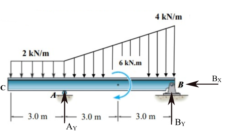
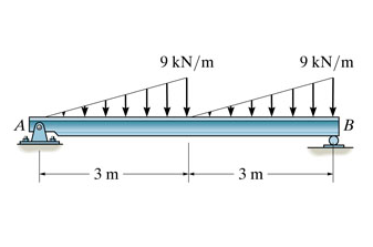
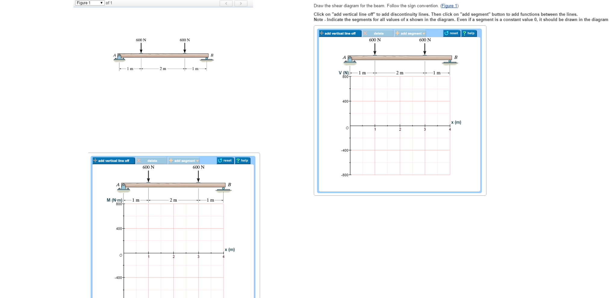
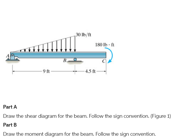
PART A Draw the shear diagram for the beam. Follow the sign convention. (Figure 1) Click on "add vertical line off" to add discontinuity lines. Then click on "add segment" button to add functions between the lines. Note 1 - You should not draw an "extra" discontinuity line at the point where the curve passes the x-axis.
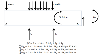
Draw the shear diagram for the beam. follow the sign convention
Ask any question and get an answer from our subject experts in as little as 2 hours. In order to continue enjoying our site, we ask that you confirm your identity as a human. Thank you very much for your cooperation Answer to Solved - Draw the shear diagram for the beam. Follow the. ... Follow the sign convention. - Draw the moment diagram for the beam. Follow the sign ...
Draw the shear diagram for the beam. follow the sign convention. 1 week ago - Free online beam calculator that calculates the reactions, deflection and draws bending moment and shear force diagrams for cantilever or simply supported beams In order to continue enjoying our site, we ask that you confirm your identity as a human. Thank you very much for your cooperation Step 2 of 3. (A) Draw the free body diagram of the section of the beam at the range as shown in Figure (3). Here, horizontal location on the beam with respect to point A is x and the maximum magnitude of distributed load at the x location is y. Determine expression for the maximum magnitude of distributed load ( y) using similar triangles rule ... Answer to Draw the shear diagram for the beam. Follow the sign convention. Draw the moment diagram for the beam. Follow the sign c...
(Figure 1) Follow the sign convention. Draw the shear diagram for the beam. Draw the moment diagram for the beam. 300 N 0.5 m 1200 N/m 1 m 600 N 0.5 m Posted 3 months ago. View Answer Draw the shear force and moment diagrams for the beam The supports at A and B are a thrust and journal bearing, respectively. ... 2 weeks ago - Most of the people that deal with the mechanics of materials are generally confused with the directions and sign conventions of shear forces and bending moments. Part B Draw the moment diagram for the beam. Follow the sign convention. This problem has been solved! See the answer ... Today we will see here the sign conventions for shear force and bending moment diagram in subject of strength of materials with the help of this post. ... Let us consider that we have one beam AB and we have assumed one section XX as displayed in following figure.
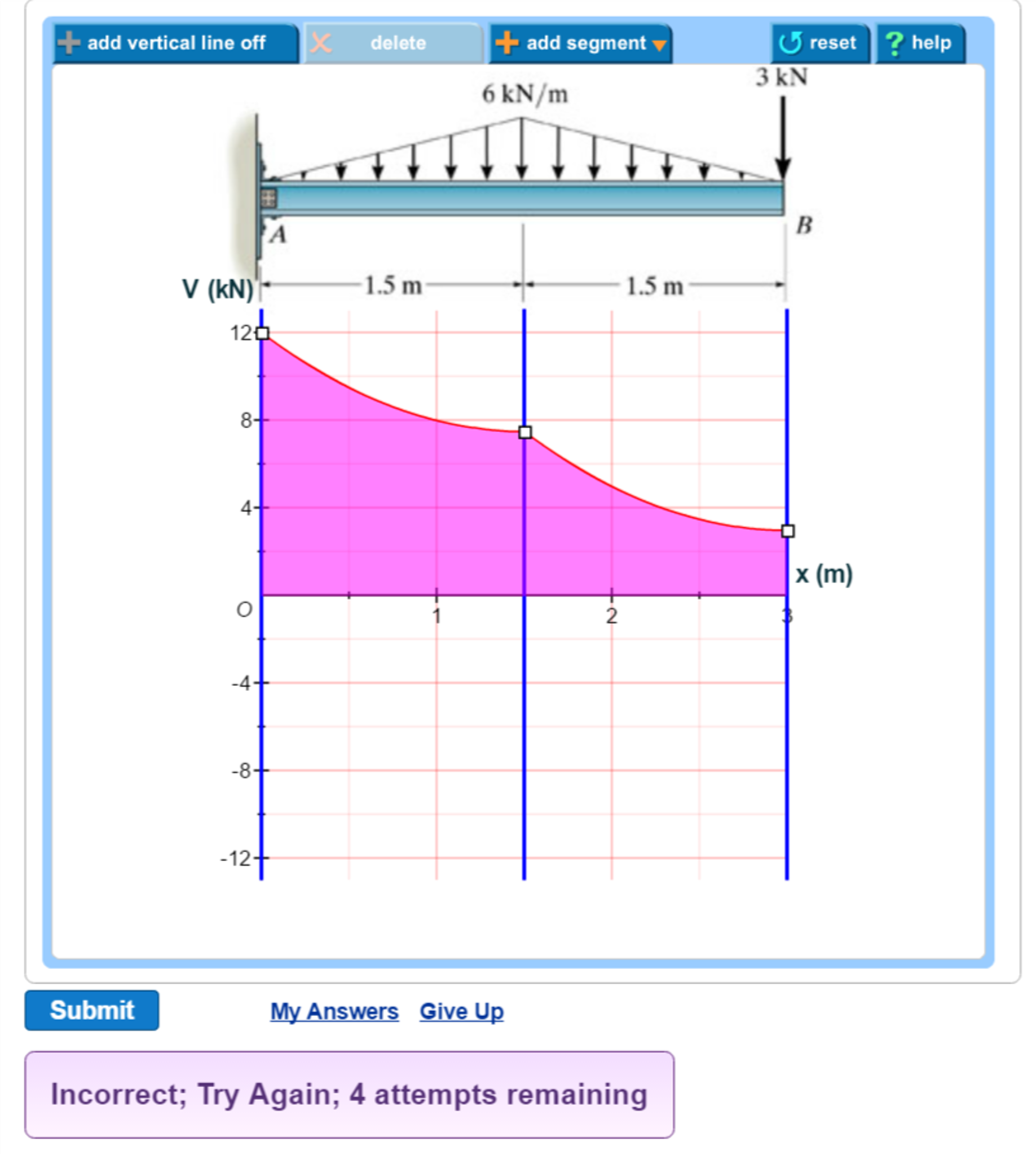
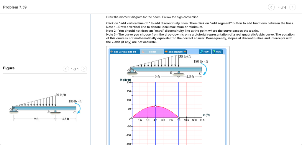
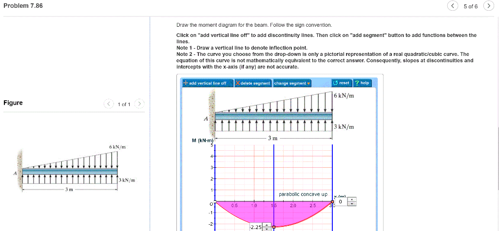
Draw the moment diagram for the beam. Follow the sign convention. The wrong answers keep getting posted. On the sheer diagram the values tested are A=12, Midpoint=7.5, B=3. On the moment diagram the values are A=-22.5, Midpoint=-6.75, B=0. I have tested both concave up and concave down in these scenarios. Follow the sign convention. (Figure 1) Problem 7.59 Part B Draw themoment diagram for the beam. Follow the sign convention. This problem has been solved! ... Draw the shear diagram for the beam. Follow the sign convention. (Figure 1) Problem 7.59 Part B Draw themoment diagram for the beam. (Figure 1) Part B Draw the moment diagram for the beam. Follow the sign convention. This problem has been solved! See the answer ... Drexel University Information Technology provides university-wide instructional, administrative, and research services. Learn more about Personal Web Page today.
Draw the shear diagram for the beam. Follow the sign convention. Then click on "add segment" button to add functions between the lines. Note 1- Make sure you place only one vertical line at places that require a vertical line. Note 2 - You should not draw an "extra" discontinuity line at the point where the curve passes the x-axis.
Answer to Draw the shear diagram for the beam. Follow the sign convention. (Figure 1)...
Draw the shear diagram for the beam. Follow the sign convention. (Figure 1) Click on "add vertical line off" to add discontinuity lines. Then click on "add segment" button to add functions between the lines. Note 1 - You should not draw an "extra" discontinuity line at the point where the curve passes the x-axis.
Draw the shear diagram for the beam. Follow the sign convention. (Figure 1) Click on "add vertical line off" to add discontinuity lines. Then click on "add segment" button to add functions between the lines. Note 1 - You should not draw an "extra" discontinuity line at the point where the curve passes the x-axis.
This problem has been solved! ... ?Draw the shear diagram for the beam. Follow the sign convention. Show transcribed image text. Expert Answer. Who are the ...
The following are the important types of beams: 1. Cantilever beam, 2. Simply supported beam, ... Sign convention of SF and BM For Shear force: We shall remember one easy sign convention, i.e., to the right side of a section, external force ... and B.M. diagrams for the cantilever beam. Shear Force Diagram S.F. at D, F D = + 800 N S.F. at C, F ...
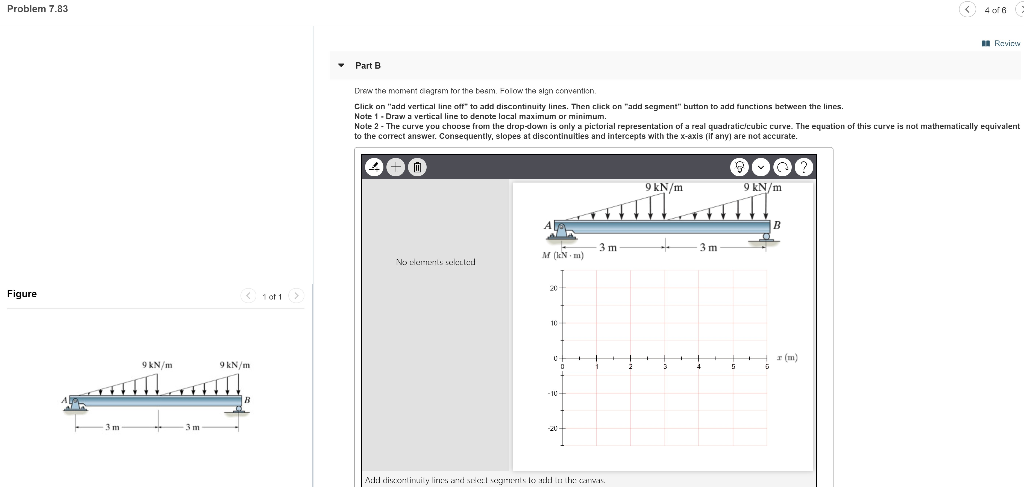
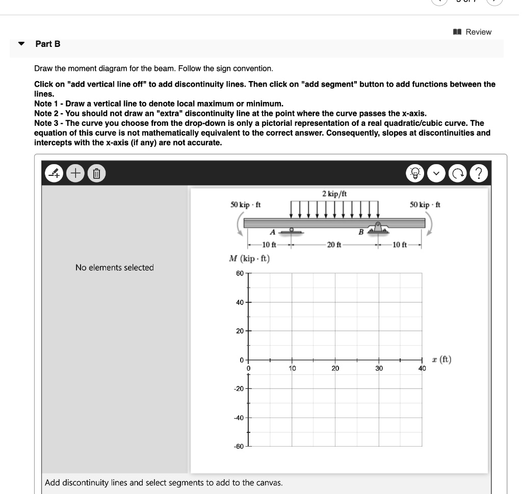
B) Draw the moment diagram for the beam. Follow the sign convention. Show transcribed image text. Expert Answer.
Problem 7.77 Part A Draw the shear diagram for the beam. Follow the sign convention. (Figure 1) Click on "add vertical line off" to add discontinuity lines. Then click on "add segment" button to add functions between the lines Note 1- You should not draw an "extra" discontinuity line at the point where the curve passes the x-axis Note 2 Be sure ...
Part A Draw the shear diagram for the beam. Follow the sign convention. (Figure 1) Click on "add vertical line off" to add discontinuity lines. Then click on "add segment" button to add functions between the lines.
In order to continue enjoying our site, we ask that you confirm your identity as a human. Thank you very much for your cooperation
Computer Science. Computer. Question #128186. Draw the shear diagram for the beam. follow the sign convention. Computer. 1484 students attemted this question. Bookmark. Add Comment. Share With Friends.
Question: Problem 7.76 Part A Draw the shear diagram for the beam. Follow the sign convention. (Figure 1) Click on "add vertical line off" to add discontinuity lines. Then click on "add segment" button to add functions between the lines. Note 1 Note 2 - Be sure to indicate the correct types of the functions between the lines, e.g. as incorrect.
Follow the sign convention. Forces in beams beams various. If there is a downward point load and no support than the shear force diagram will start as a negative at the value of the point load. Then click on add segment button to add functions between the lines note 1 draw a vertical line to denote local maximum or minimum. Then click on add ...
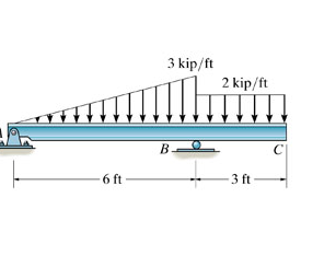
We've got the study and writing resources you need for your assignments. Start exploring! Engineering Civil Engineering Q&A Library Draw the shear diagram for the beam. Follow the sign convention. 6 kN 12 kN/m 6 m 3 m. Draw the shear diagram for the beam. Follow the sign convention. 6 kN 12 kN/m 6 m 3 m.
Topics covered include basic concepts of mechanics and vectors, Free-Body diagrams and equilibrium of particles, Free-Body diagrams and equilibrium of rigid bodies, force systems, analysis of trusses, beams and frames, distributed forces, centroids and moments of inertia, internal shear and bending ...
This page uses frames, but your browser doesn't support them
December 30, 2017 - Answer (1 of 10): Sad to notice how some of the answers define bending moment as clockwise and anticlockwise. It’s like, you take a rod in your hand and bend it with one hand by moving your hand clockwise or anticlockwise. But with one hand, you can surely rotate it, but not bend.
Transcribed image text: Problem 7.59 Part A Draw the shear diagram for the beam. Follow the sign convention. (Figure 1) Click on "add vertical line off" to ...
Question: Draw the shear and moment diagram for the beam.Problem 7-71 from:Engineering Mechanics: Statics, 14th editionRussell C. HibbelerThank you guys for ...
January 8, 2021 - 1 Answer to Problem 7.70 Draw the shear diagram for the beam. Follow the sign convention. (Figure 1) Click on "add vertical line off" to add discontinuity lines. Then click on "add segment" button to add functions between the lines add vertical line off delete + add segment â–¼ reset ? ...
(Figure 1) Part B Draw the moment diagram for the beam. Follow the sign convention. This problem has been solved! See the answer ...
Part B Draw the moment diagram for the beam. Follow the sign convention. HW18 Problem 7.71 Resources Problem 7.71 Part A Draw the shear diagram for the beam. Follow the sign convention. (Figure 1) Click on "add vertical line off" to add...
Structural member are cut into sections when analysing and typical sign convention is... Sagging bending moment is positive, Hogging bending moment is negati...
Problem 7.80 3 of 3 Draw the shear diagram for the beam. Follow the sign convention. (Figure 1) Click on "add vertical line off" to add discontinuity lines. Then click on "add segment" button to add functions between the lines. Note 1 You should not draw an "extra" discontinuity line at the point where the curve passes the x-axis.
beam from the left hand end and summing up the areas of shear force diagrams using proper sign convention. xThe process of obtaining the moment diagram from the shear force diagram by summation is exactly the same as that for drawing shear force diagram from load diagram.
Problem 7.84 Draw the moment diagram for the beam. Follow the sign convention. Click on "add vertical line off" to add discontinuity lines. Then click on "add segment" button to add functions between the lines. Note 1 - Draw a vertical line to denote local maximum or minimum.
Part B Draw the moment diagram for the beam. Follow the sign convention. This problem has been solved! See the answer ...
Answer to Solved - Draw the shear diagram for the beam. Follow the. ... Follow the sign convention. - Draw the moment diagram for the beam. Follow the sign ...
In order to continue enjoying our site, we ask that you confirm your identity as a human. Thank you very much for your cooperation
Ask any question and get an answer from our subject experts in as little as 2 hours.
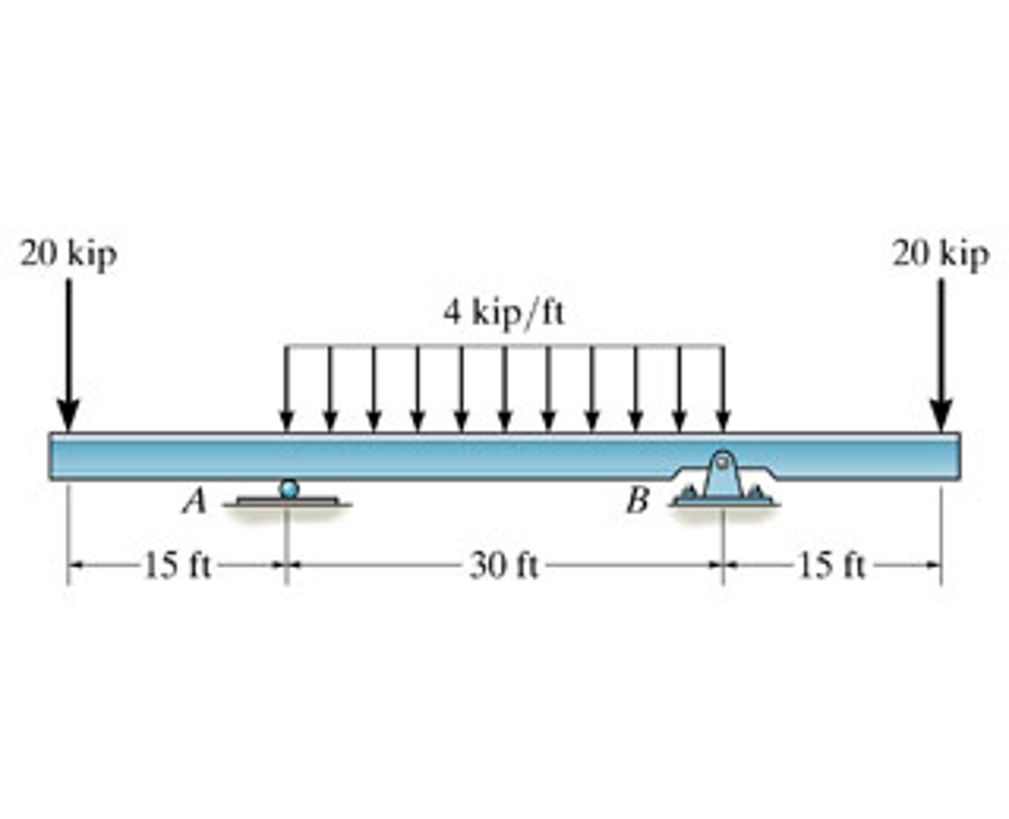
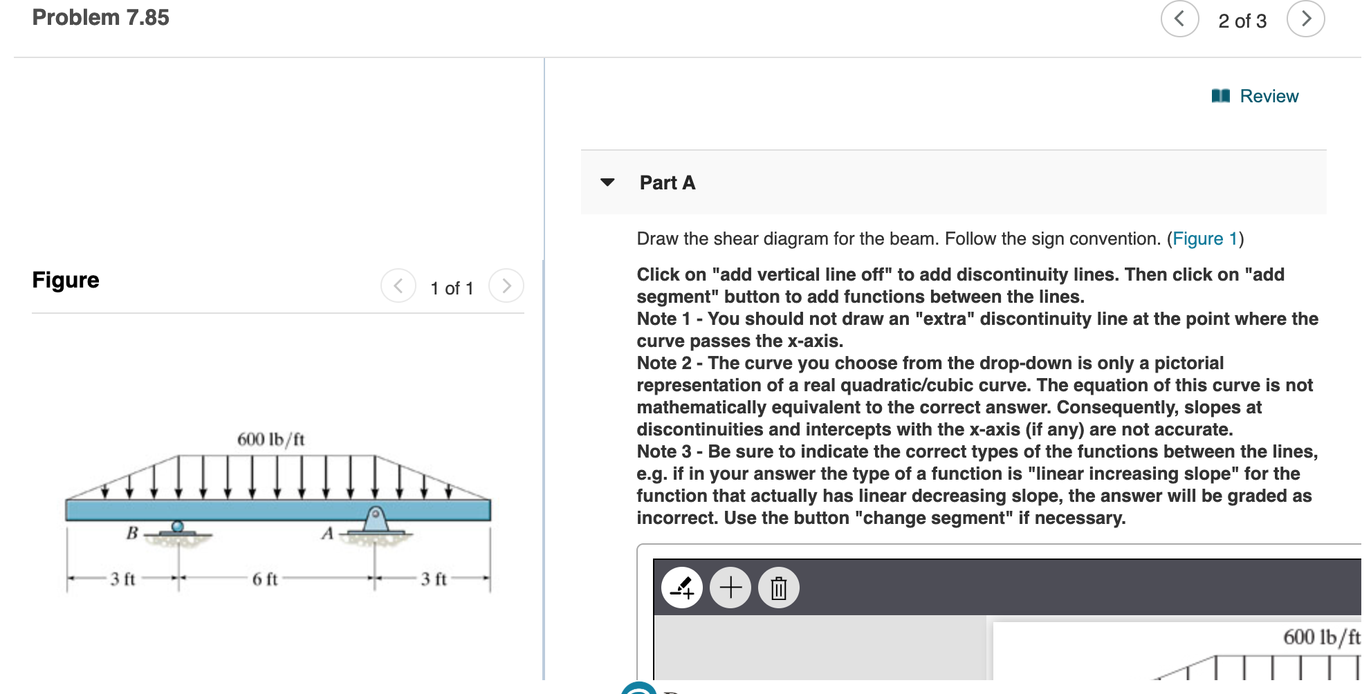

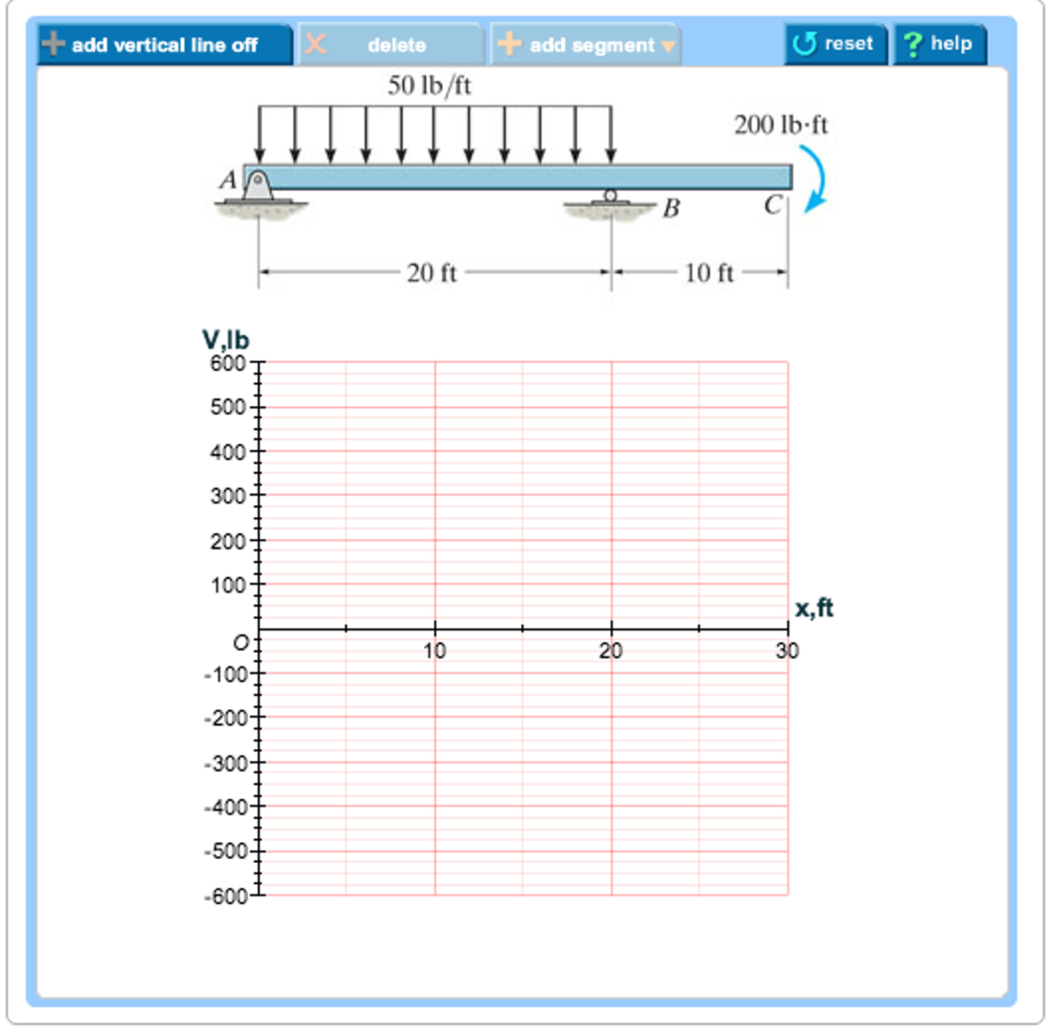












0 Response to "37 draw the shear diagram for the beam. follow the sign convention"
Post a Comment