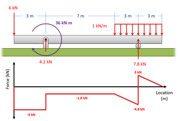
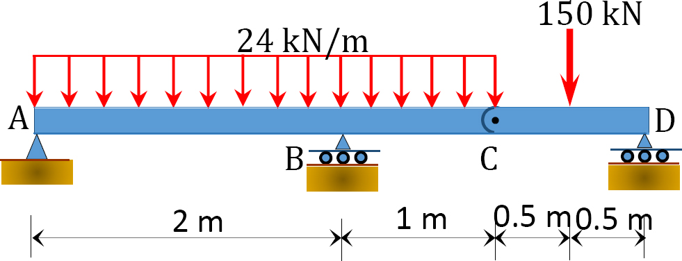
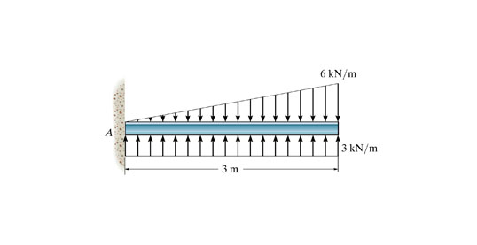
37 choose the correct shear diagram for the beam. follow the sign convention.
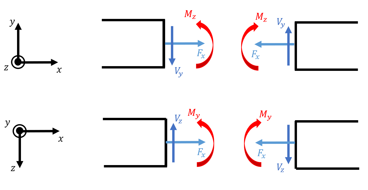
Get 24⁄7 customer support help when you place a homework help service order with us. We will guide you on how to place your essay help, proofreading and editing your draft – fixing the grammar, spelling, or formatting of your paper easily and cheaply. As a convention, the shearing force diagram is plotted above or below a line corresponding to the neutral axis of the beam, but a plus sign must be indicated if it is a positive shearing force, and a minus sign should be indicated if it is a negative shearing force.
shear force and bending moment and also some basic concepts of strength of materials in our recent posts. We have already seen the various types of beams and different types of loads on beam during our previous posts. Today we will see here the sign conventions for shear force and bending moment diagram in subject of strength of materials with the help of this post.

Choose the correct shear diagram for the beam. follow the sign convention.
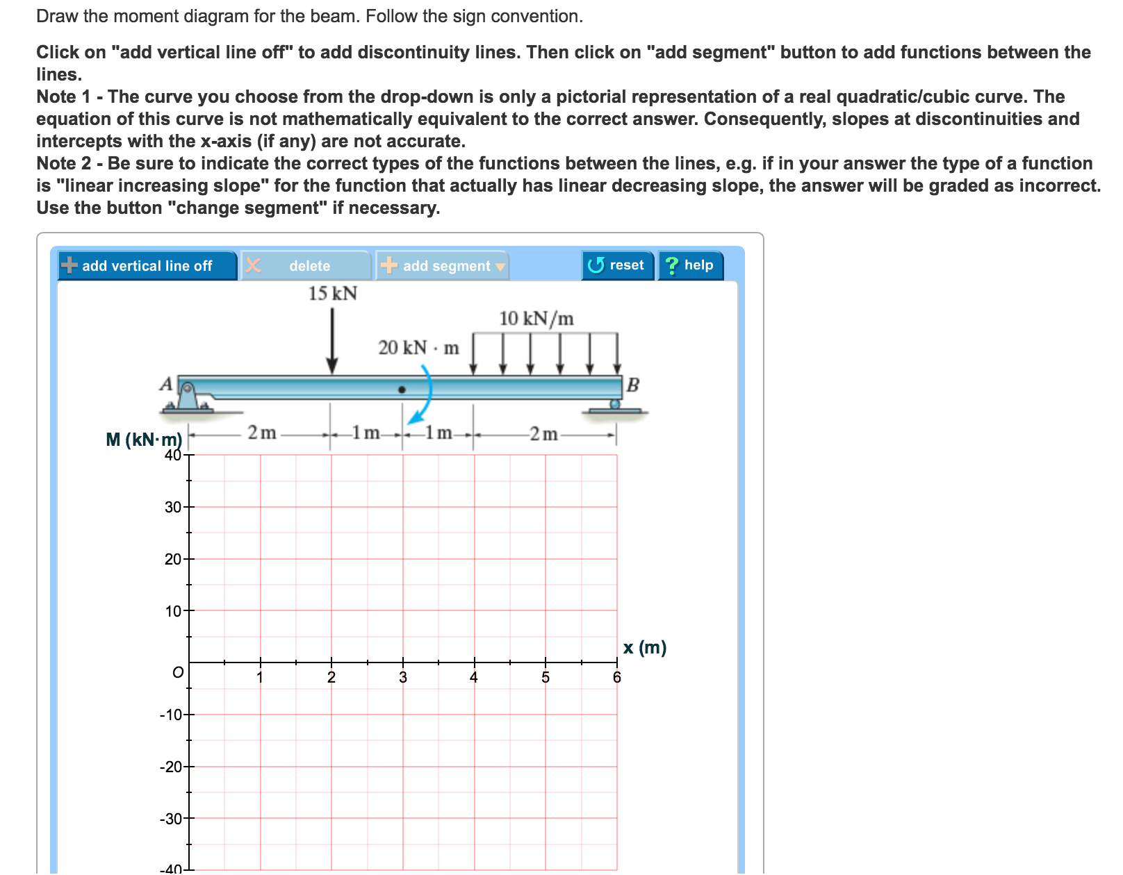
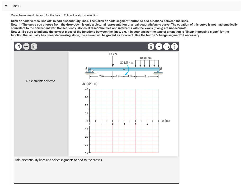
Based on this sign convention, the shear force at the section cut for the example cantilever beam in the figure above is positive since it causes clockwise rotation of the selected section. The moment is negative since it compresses the bottom of the beam and elongates the top (i.e., it makes the beam "frown"). ANSWER: 315 Correct Problem 7.81 The beam consists of three segments pin connected at and. = 1.76 = 315 Part A Draw the shear diagram for the beam. Follow the sign convention. Consider the beam shown in (Figure 1). Follow the sign convention. Draw the moment diagram for the beam. Click on "add vertical line off" to add discontinuity lines. Then click on "add segment" button to add functions between the lines. Note 1 - Draw a vertical line to denote local maximum or minimum.
Choose the correct shear diagram for the beam. follow the sign convention.. Draw the shear diagram for the beam. Follow the sign convention. (Figure 1) Click on "add vertical line off" to add discontinuity lines. Then click on "add segment" button to add functions between the lines. Note 1 - Make sure you place only one vertical line at places that require a vertical line. 1 Answer to Draw the moment diagram for the beam DE. Follow the sign convention for the internal loadings in the beam shown in the figure below. Click on "add vertical line off' to add discontinuity lines. Then click on "add segment" button to add functions between the lines. Note 1 - The curve you choose from... Solution for Draw the shear diagram for the beam. Follow the sign convention. Draw the moment diagram for the beam. Follow the sign convention. close. Start your trial now! First week only $4.99! arrow ... In this question we need to choose a correct option. Sign in. Order now. Easy way to better grades. We write custom essay samples to help international students succeed with their studies Order your paper. Grades. We will help you score well in that assignment! 96%. our average grade score. We always make sure that writers follow all your instructions precisely. You can choose your academic level: high school, …
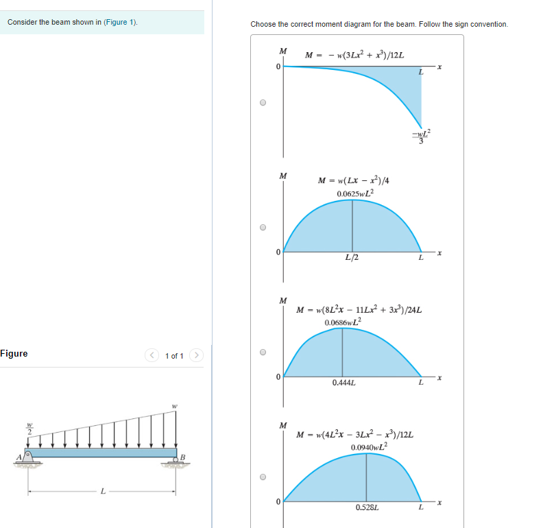
Take your hands and twist at each end of an imaginary member in the air to put tension due to bending on the same side as the diagram, the twist direction your hands are making is the direction/sign convention of the moment (EDIT - at any point on the beam). RE: Sign Convention ! 271828 (Structural) 23 May 19 02:13. Choose the correct shear diagram for the beam. Follow the sign convention V - - w (6Lx + 3x)/12L -32 V = w (4L2 - 6Lx - 3x?)/12L 0.528. Figure 1 of 1 > V = - 3wx/4 -32 V = w (4L - 9x)/12 0.4445 Consider the beam shown in (Figure 1). Choose the correct moment diagram for the beam. Follow the sign convention. Problem 7.84 Draw the moment diagram for the beam. Follow the sign convention. Click on "add vertical line off" to add discontinuity lines. Then click on "add segment" button to add functions between the lines. Note 1 - Draw a vertical line to denote local maximum or minimum. Choose the correct moment diagram for the beam. Follow the sign convention. It is a cubic curve that starts at zero and has a negative increasing slope. ... Choose the correct shear diagram for the beam. Follow the sign convention. x=1.005 m.
Part A Choose the correct shear diagram for the beam. Follow the sign convention. ... Correct Part B Choose the correct moment diagram for the beam. Follow the sign convention. ANSWER: ANSWER : Correct Problem 7.78 Part A Draw the shear diagram for the beam. Share this link with a friend: Copied! Other Related Materials. 01.11.2021 · f) Asymmetrical folds in a shear zone, indicating sense of shear. g) Example of extensional fold developed in the hangingwall to a 10 km displacement fault in the North Sea rift basin. The fold is related to the non-planar fault geometry. Differential compaction above the hangingwall also produce a very gently fold seen at the base of the post-rift sequence. h) … Password requirements: 6 to 30 characters long; ASCII characters only (characters found on a standard US keyboard); must contain at least 4 different symbols; Answer (1 of 11): You are NOT free to choose any sign convention you want: Positive moment is that which a simply supported beam experiences when loaded with gravity loads. See the middle diagram in red below: A negative deflection is experienced when the beam sags in the direction of the gravi...
Continuous Beam - an overview | ScienceDirect Topics
Mechanics of Materials . Enter the email address you signed up with and we'll email you a reset link.
Materials | Free Full-Text | Behavior of Steel–Coconut Shell ...
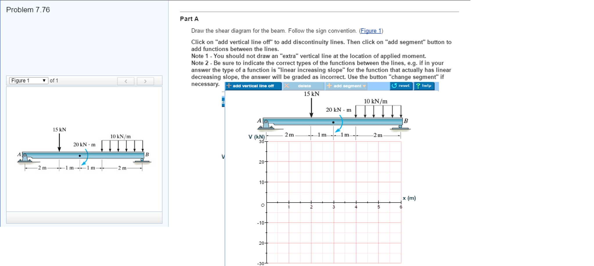
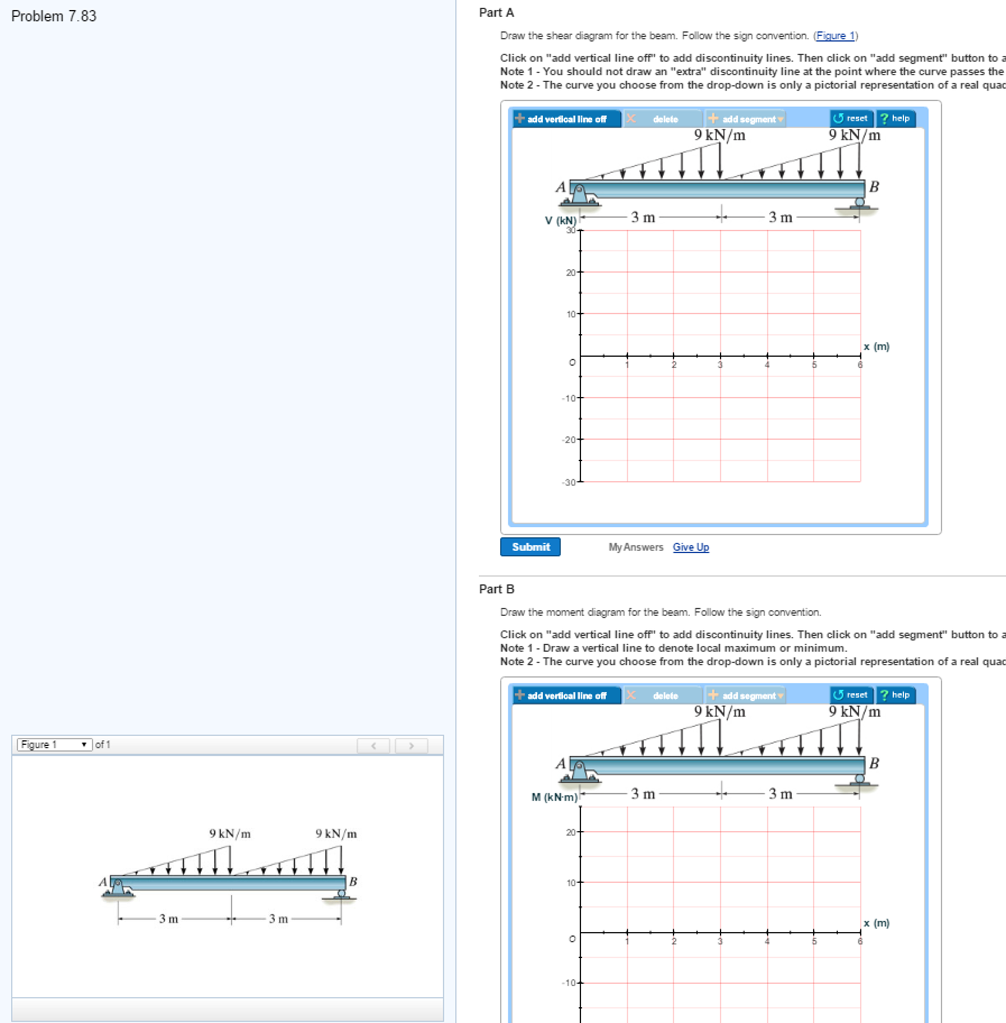
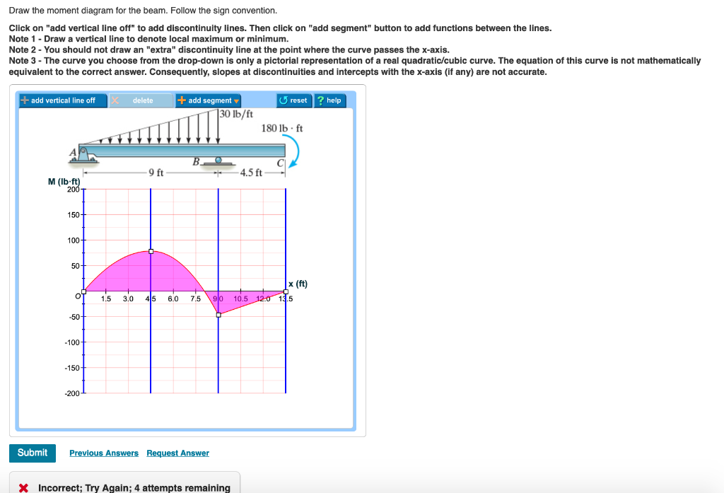
Draw the shear diagram for the beam. Follow the sign convention. (Figure 1) Click on "add vertical line off" to add discontinuity lines. Then click on "add segment" button to add functions between the lines. Note 1 - You should not draw an "extra" discontinuity line at the point where the curve passes the x-axis.
The Ultimate Guide to Shear and Moment Diagrams ...
4.2 Notation and sign convention xShear force (V) Positive Shear Force A shearing force having a downward direction to the right hand side of a section or upwards to the left hand of the section will be taken as 'positive'. It is the usual sign conventions to be followed for the shear force. In some book followed totally opposite sign ...
6.2 Shear/Moment Diagrams – Engineering Mechanics: Statics
The three most prominent internal forces in structural analysis calculations are the bending moment, shear force, and axial force. It is very common for people to define and state their sign convention before proceeding with any structural analysis problem. This is mainly due to variations in the selection of positive and negative coordinates.

Inverting the structure–property map of truss metamaterials ...
Part A Draw the shear diagram for the beam. Follow the sign convention. (Figure 1) Click on "add vertical line off" to add discontinuity lines. Then click on "add segment" button to add functions between the lines.

answers are correct just need clarification on the work to ...
Shear and Bending Moment Diagrams: The loading on most beams is such that the stress resultant on planes perpendicular to the axis of the beam consists of a shear force, V, and a bending moment, M. In determining beam responses, it is very convenient, if not essential, to first determine the shear and bending moment diagrams.

Use the graphical method to construct the shear-force and ...
Part A Consider the beam shown in (Figure 1). Follow the sign convention. Draw the shear diagram for the beam Click on "add vertical line off" to add discontinuity lines. Then click on "add segment" button to add functions between the lines. ... Note 2 - Be sure to indicate the correct types of the functions between the lines, e.g. if ...
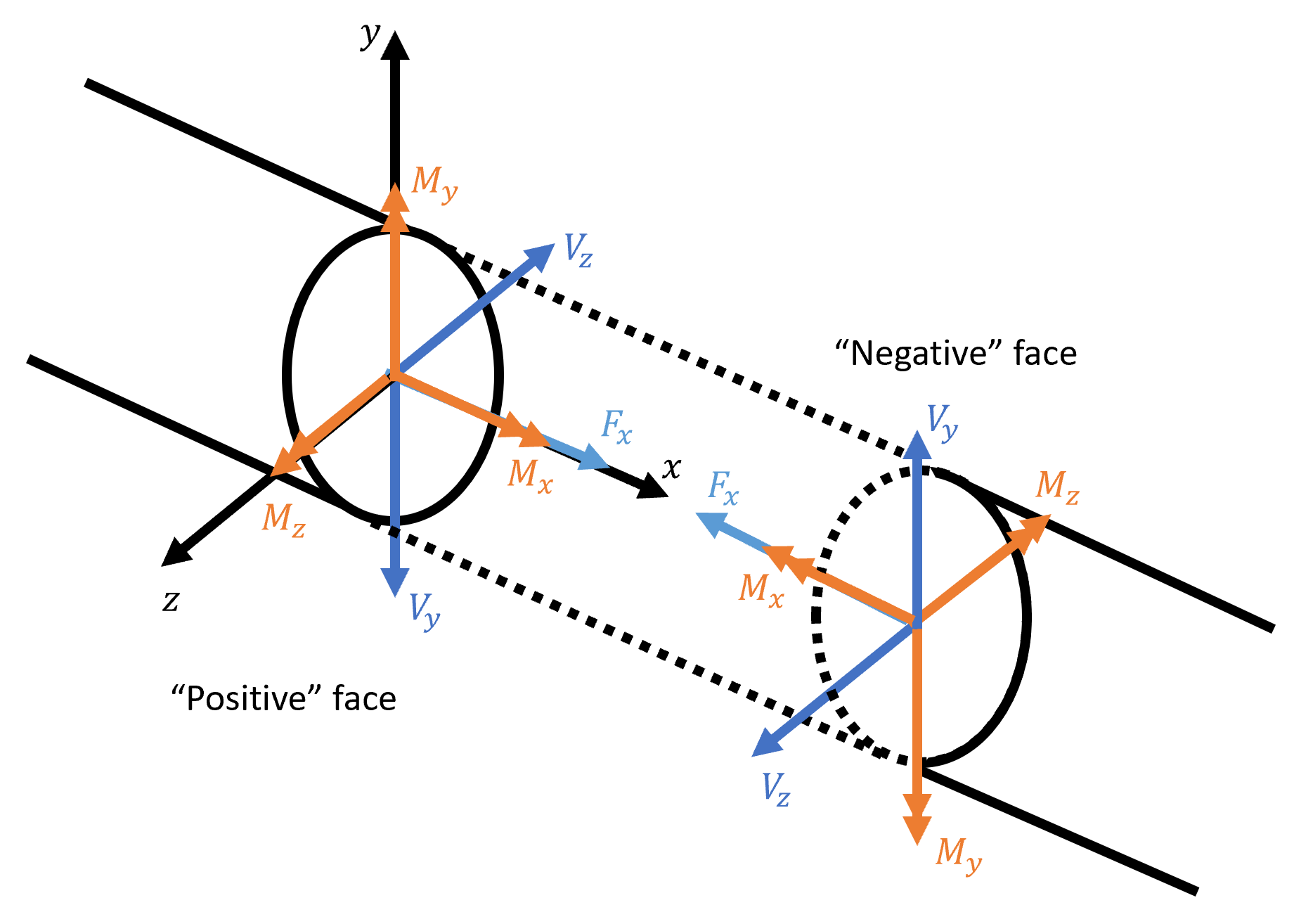
Sign Convention
Academia.edu is a platform for academics to share research papers.
MCA | Free Full-Text | A Saint-Venant Model for Overland ...
20.10.2017 · Advanced beam topics, such as composite and curved beams, unsym- metrical bending, and shear center, appear in chapters that are distinct from the basic beam theory. This makes it convenient for instructors to . choose only those topics that they wish to present in their course. Chapter 12, entitled ‘‘Special Topics,’’ consolidates topics that are important but not …
Solved Draw the shear diagram for the beam. Follow the sign ...
We always make sure that writers follow all your instructions precisely. You can choose your academic level: high school, college/university or professional, and we will assign a writer who has a respective degree. Professional and Experienced Academic Writers. We have a team of professional writers with experience in academic and business writing. Many are native …

Performed tempo by stylistic criterion vs. Beethoven's marks ...
But when I'm drawing my shear diagram, cutting my beam from left to right, I struggle to figure out which direction to draw my shear. My 1960's statics textbook is good but doesn't quite explain it. If I choose the "wrong way" as my textbook examples, then my moment diagram has the wrong sign.

Internal Shear Force - an overview | ScienceDirect Topics
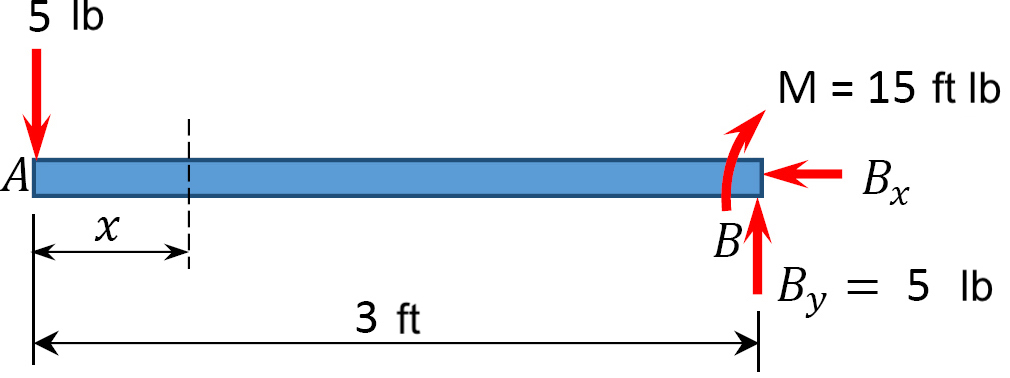
See the answer. Consider the beam shown in (Figure 1). The support at A offers no resistance to vertical load. Part A Choose the correct shear diagram for the beam. Follow the sign convention. Choose the correct shear diagram for the beam. Follow the sign convention. SubmitRequest Answer Part B Choose the correct moment diagram for the beam.
RISA-3D
To create a Shear-Moment Diagram you need to assess the support conditions and calculate the reactions from a beam table. Then plot the internal shear force in the beam as it changes along its length. This curve can then be integrated to determine the moment at any point. Sign Convention

Part A Draw the shear diagram for the beam. Follow the sign ...
PART A Draw the shear diagram for the beam. Follow the sign convention. (Figure 1) Click on "add vertical line off" to add discontinuity lines. Then click on "add segment" button to add functions between the lines. Note 1 - You should not draw an "extra" discontinuity line at the point where the curve passes the x-axis.
Solved Part A Draw the shear diagram for the beam. Follow ...
handbook. on reinforcement and detnling. bureau of indian standards manak bhavan. 9 bahadur 8hah 2afar marg new delhi110 002 sp 34 : 1987. first published august 1987 first reprint december 1992 t second reprint november 1995 third reprint december 1996 fourth reprint july 1997 fifth reprint march 1999. 0 bureau of indian stand.4rds
Part A Draw the shear diagram for the beam. Follow | Chegg.com
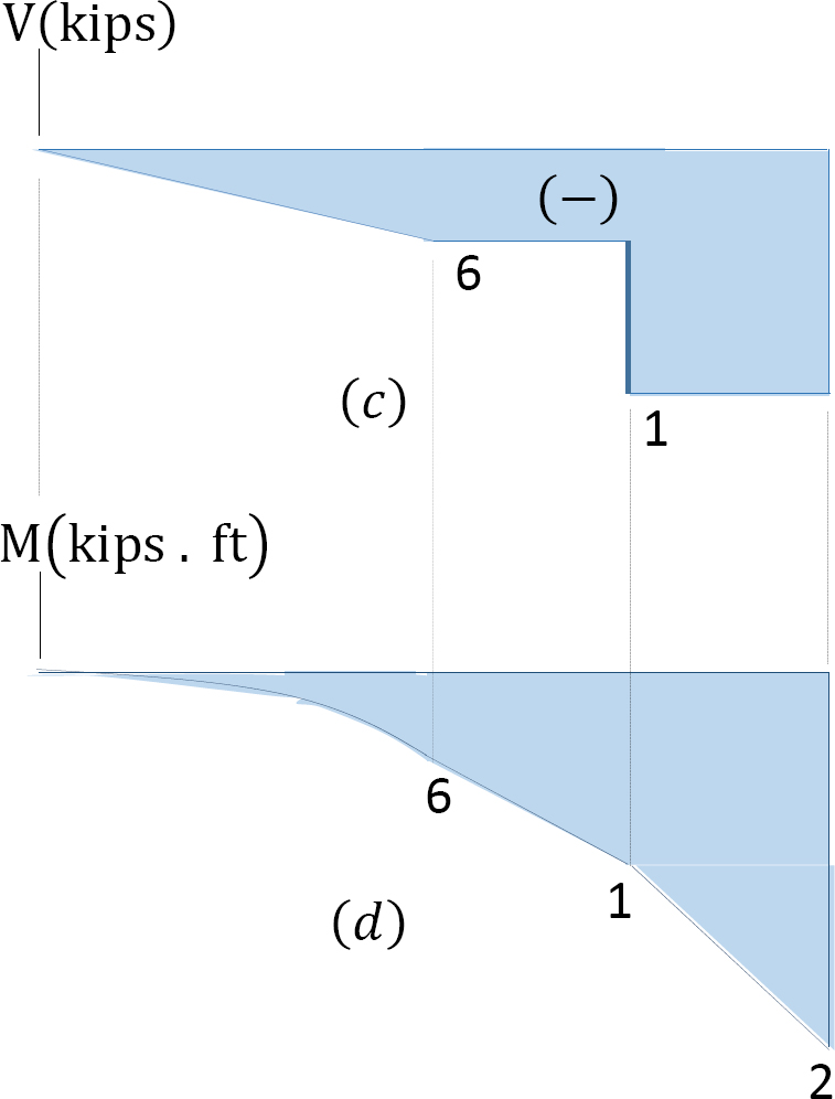
desirable to draw the V-diagram below the FBD of the entire beam, and then draw the M-diagrambelow the V-diagram. The bending moment and shear force diagrams of the beam are composites of the V and M diagrams of the segments. These diagrams are usually discontinuous, or have discontinuous slopes.
Solved Draw the shear diagram for the beam. Follow the sign ...
Choose a trusted paper writing service. Save your time. Score better. Simply kick back and relax. Coursework Hero will take good care of your essays and research papers, while you’re enjoying your day. Download it! Hi there! Work’s Done. Calculate your order. Type of paper. Academic level. Deadline. Pages (275 words) − + Standard price: $ 0.00. Client Reviews 4.9. Sitejabber …
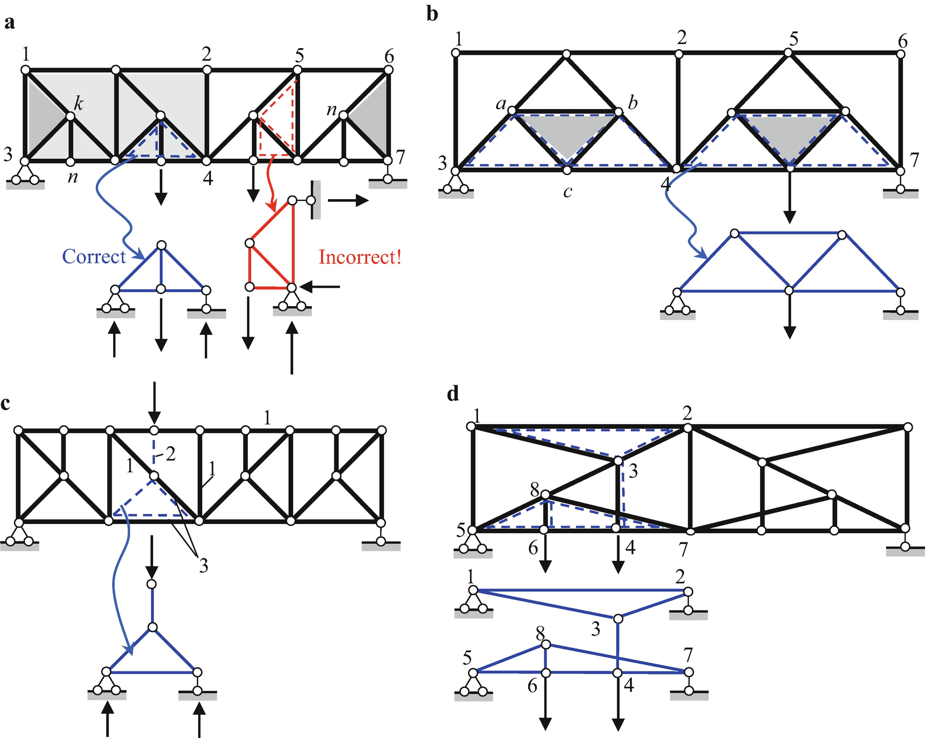
Plane Trusses | SpringerLink
Consider the beam shown in (Figure 1). Follow the sign convention. Draw the moment diagram for the beam. Click on "add vertical line off" to add discontinuity lines. Then click on "add segment" button to add functions between the lines. Note 1 - Draw a vertical line to denote local maximum or minimum.

Draw the shear diagram for the beam. Follow the sign convent
ANSWER: 315 Correct Problem 7.81 The beam consists of three segments pin connected at and. = 1.76 = 315 Part A Draw the shear diagram for the beam. Follow the sign convention.
Solved Part A> Draw the shear diagram for the beam ...
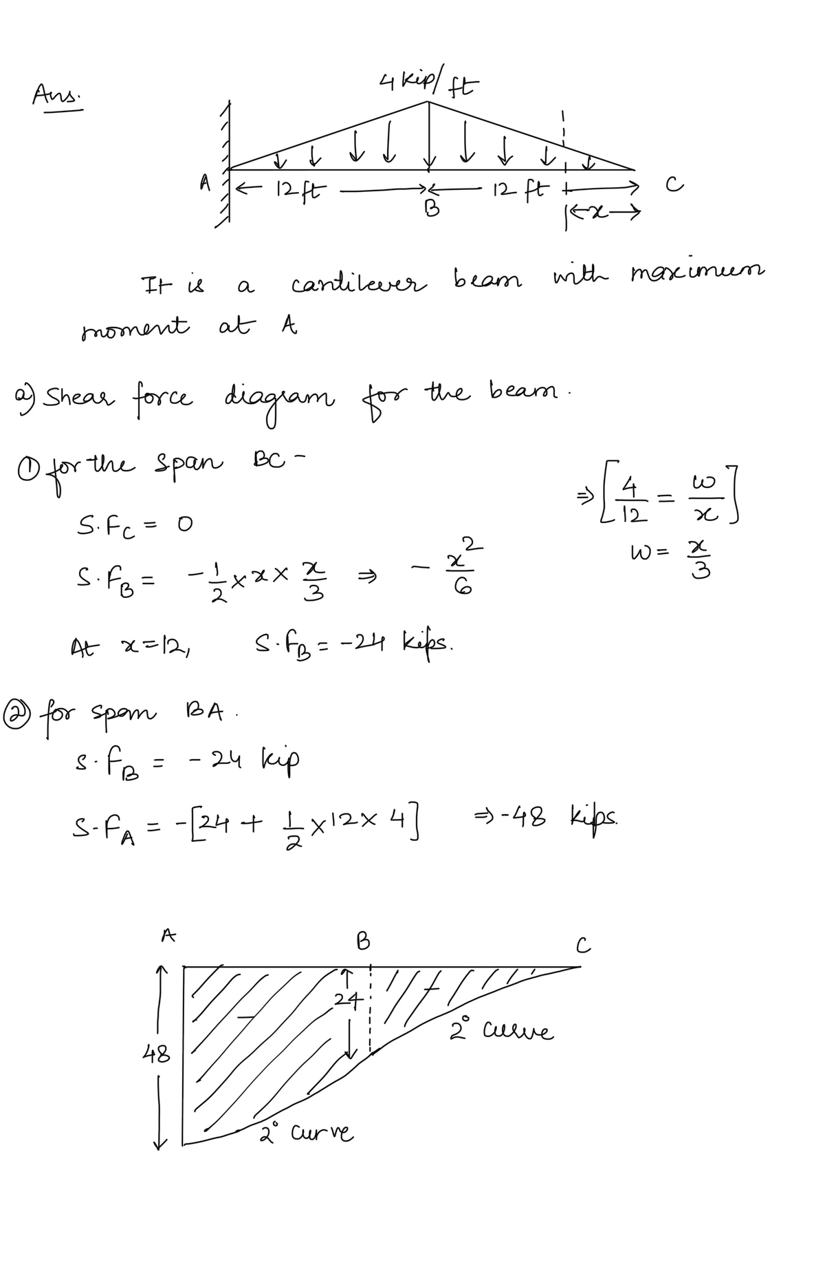
Based on this sign convention, the shear force at the section cut for the example cantilever beam in the figure above is positive since it causes clockwise rotation of the selected section. The moment is negative since it compresses the bottom of the beam and elongates the top (i.e., it makes the beam "frown").
Solved Problem 7.87 Part A Draw the shear diagram | Chegg.com

Drawing Shear and Moment Diagrams for Beam - YouTube

Drawing Shear and Moment Diagrams for Beam
Solved Draw the shear diagram for the beam. Follow the sign ...
Applied Sciences | Free Full-Text | Simulation of the ...
Sign Convention

Draw the shear diagram for the beam. Follow the sign ...
Solved Draw the shear diagram for the beam. Follow the sign ...
6.2 Shear/Moment Diagrams – Engineering Mechanics: Statics
1.4: Internal Forces in Beams and Frames - Engineering LibreTexts

Mastering Engineering, Assignment--12--Beams (Engineering ...

Part A Draw the shear diagram for the beam. Follow the sign ...

Beam Cross Section - an overview | ScienceDirect Topics
Solved Draw the shear diagram for the beam. Follow the sign ...
Answered: Draw the shear diagram for the beam.… | bartleby
6.2 Shear/Moment Diagrams – Engineering Mechanics: Statics
Solved Choose the correct shear diagram for the beam. Follow ...
0 Response to "37 choose the correct shear diagram for the beam. follow the sign convention."
Post a Comment