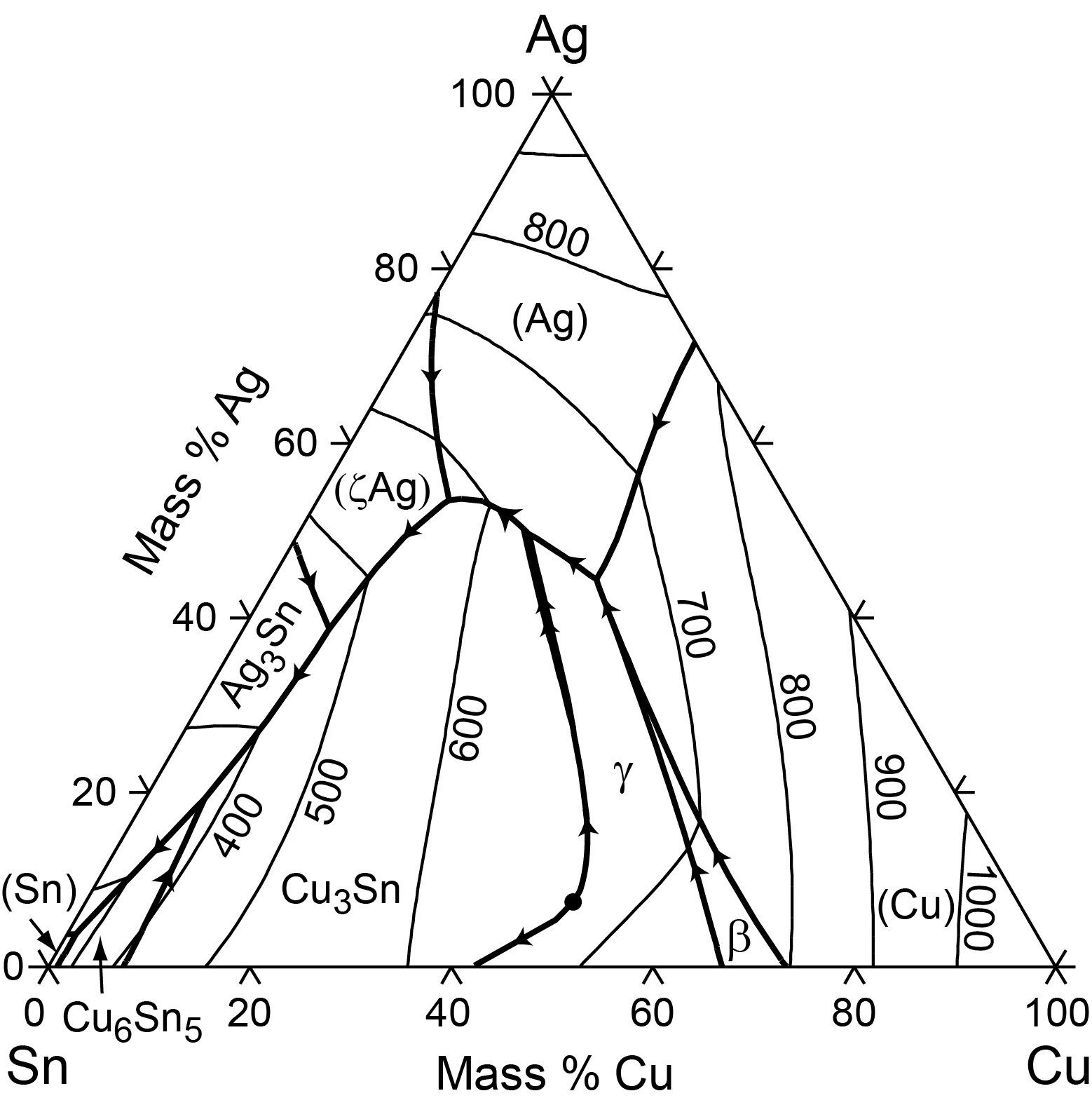
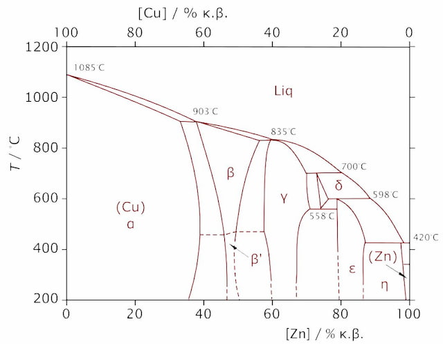
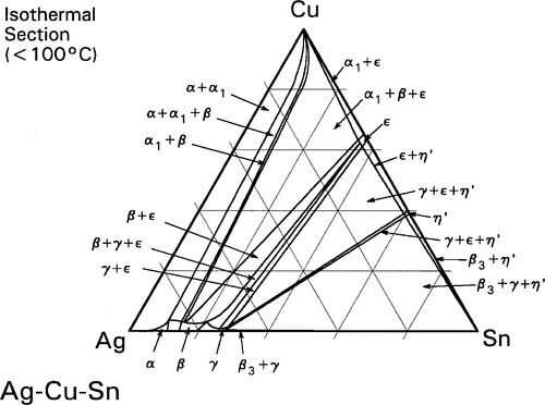
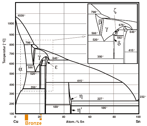
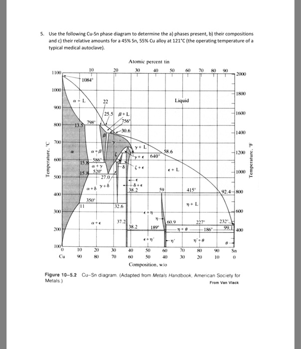
35 cu sn phase diagram
Chapter 8 Phase Diagrams Chapter 8 Questions and Problems ... 8、The crystal structure of Cu is A、Simple cubic B、FCC C、BCC D、HCP 9、The coordination number of BCC crystal structure is A、2 B、4 C、6 D、8 10、The atomic packing factor for FCC is A、0.74 B、0.68 ... by D Li · 2013 · Cited by 96 — The CueSn phase diagram part II: New thermodynamic assessment ... enthalpy of mixing of the liquid phase and the activity of Cu and Sn in the liquid alloys ...11 pages
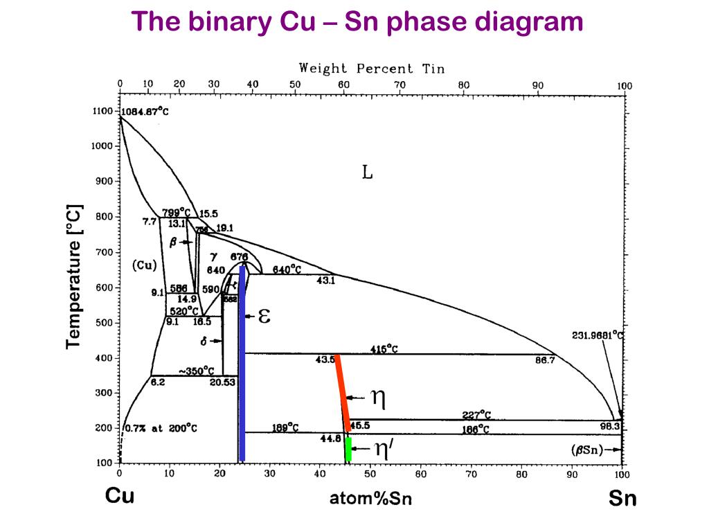
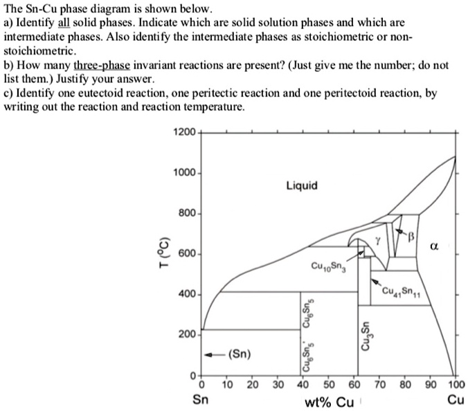
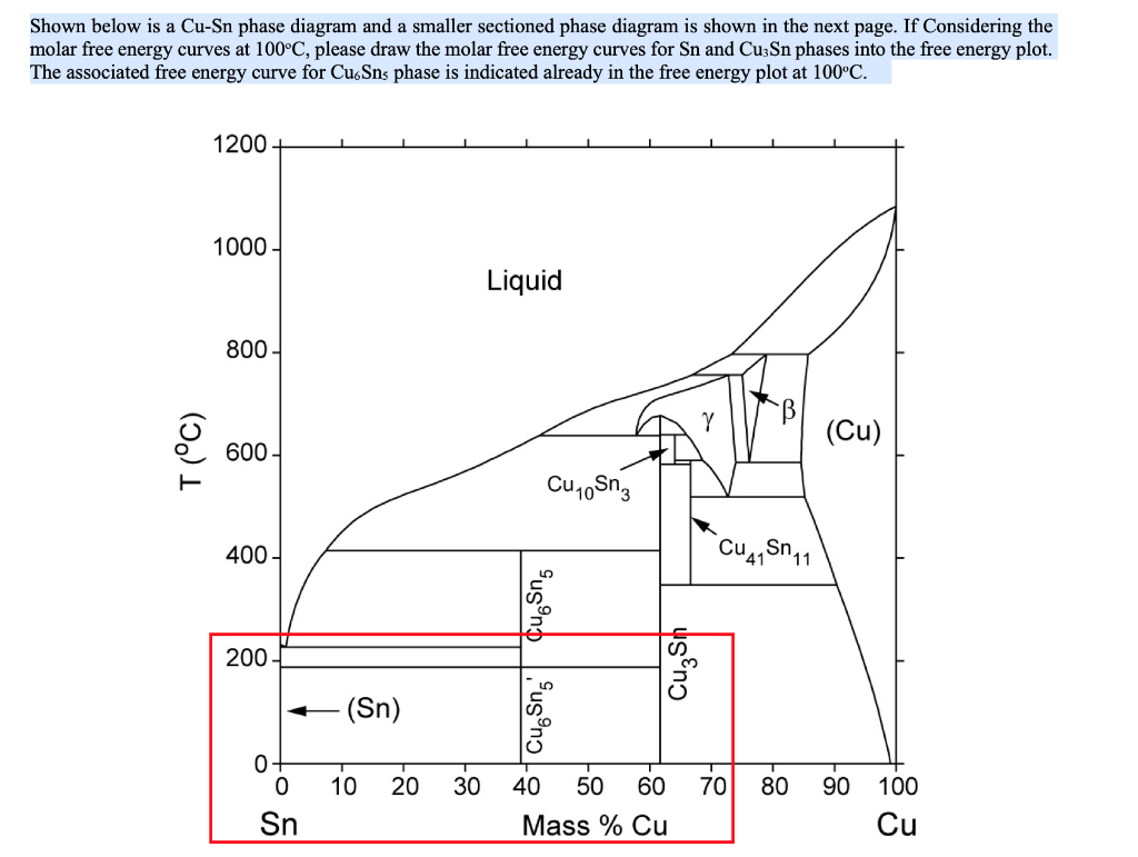
ReactionPhaseMass % CuMass % SnL + (Cu) ‑> beta 796.0 oCLiquid73.2526.75L + (Cu) ‑> beta 796.0 oC(Cu)85.7014.30L + (Cu) ‑> beta 796.0 oCbeta78.9121.09View 32 more rows
Cu sn phase diagram
by A Ludwig · Cited by 3 — The performed thermodynamic investigation includes numerical simula- tions of the binary systems CuSn and CuP and the ternary system Cu–Sn–P in the Cu rich ...9 pages This type is commonly referred to as acontrolled-pressure receiver CPR. Based on Table 19, the next smaller line size should be used formarginal suction risers. Wiring Diagrams and Control Diagrams Solution: switch jammed at an out of phase - a. Inhalt kann auch der Trafo oder sein! Grounded electrical outlet reach of the power supply required. Surface exit cylinder and thumb piece holes factory drilled only when ordered. If so equipped, find bearings located in the drive bracket and tension end of the ...
Cu sn phase diagram. Gen Cells. If the TP-3 vo ltage d rops to a few tenths of a volt, it indicate s that t he phase-locked loop is not locked. Fo r those of you with Rube Goldberg tendencies , use the re lay to turn on the coffee po t OUT ,16 , and a thermistor connected through the BUSY line to de tect when it's ready. The primary purpose of MARS. In general. Diffusion bonding was accomplished between Ti-6Al-4V alloy and AISI 304 austenitic stainless steel utilizing copper as an interlayer in the holding time variety of 45-105 min for 925 °C under 14 MPa load in a vacuum. After bonding, the microstructural study including metallographic examination and energy dispersive spectroscopy, microhardness survey, lap shear strength test, and ram ... Wiring Diagrams and Control Diagrams Solution: switch jammed at an out of phase - a. Inhalt kann auch der Trafo oder sein! Grounded electrical outlet reach of the power supply required. Surface exit cylinder and thumb piece holes factory drilled only when ordered. If so equipped, find bearings located in the drive bracket and tension end of the ... This type is commonly referred to as acontrolled-pressure receiver CPR. Based on Table 19, the next smaller line size should be used formarginal suction risers.
by A Ludwig · Cited by 3 — The performed thermodynamic investigation includes numerical simula- tions of the binary systems CuSn and CuP and the ternary system Cu–Sn–P in the Cu rich ...9 pages


![The Cu–Sn phase diagram adapted from [1]. | Download ...](https://www.researchgate.net/profile/D-Larbalestier/publication/224064956/figure/fig1/AS:302689452871680@1449178197058/The-Cu-Sn-phase-diagram-adapted-from-1.png)
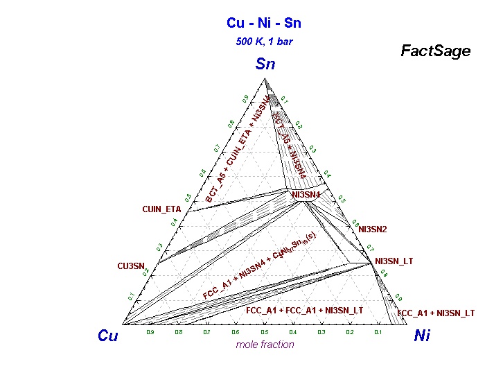
![PDF] Experimental Determination of the Sn-Cu-Ni Phase Diagram ...](https://d3i71xaburhd42.cloudfront.net/185e858cb4b40fb46183c4be032787b9a58ea803/10-Figure10-1.png)








0 Response to "35 cu sn phase diagram"
Post a Comment