39 mercruiser tilt trim wiring diagram
View and Download Mercury Optimax 115 service manual online. Direct Fuel Injection. Optimax 115 outboard motor pdf manual download. Also for: Optimax 135, Optimax 150, Optimax 175. 16-06-2017 · Wiring diagrams show the wire colors of specific parts; e.g. stop switch, stator, starter switch, alternator, engine control module, etc. Chapters and subchapters Evinrude repair manuals are divided into chapters and subchapters, also termed service manual outline.
Maintaining the Yamaha zinc, aluminum or magnesium anodes on your boat is of the utmost importance in order to keep your Yamaha outboard engine running well in the long run.

Mercruiser tilt trim wiring diagram
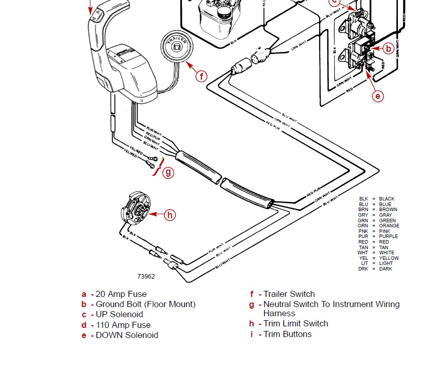
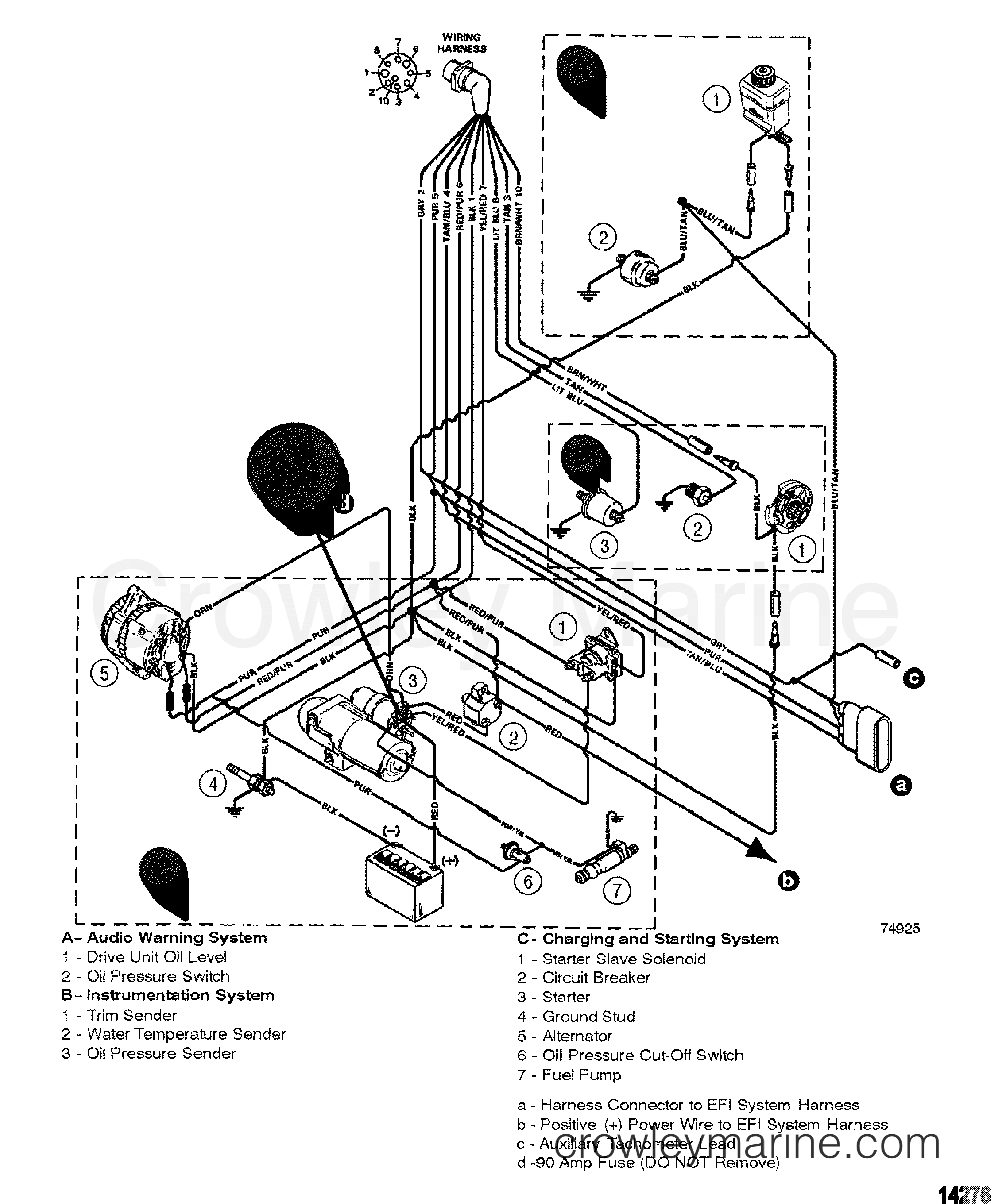
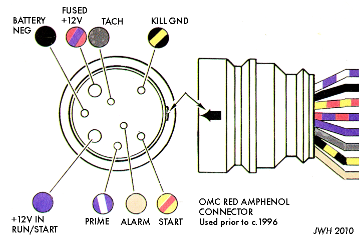
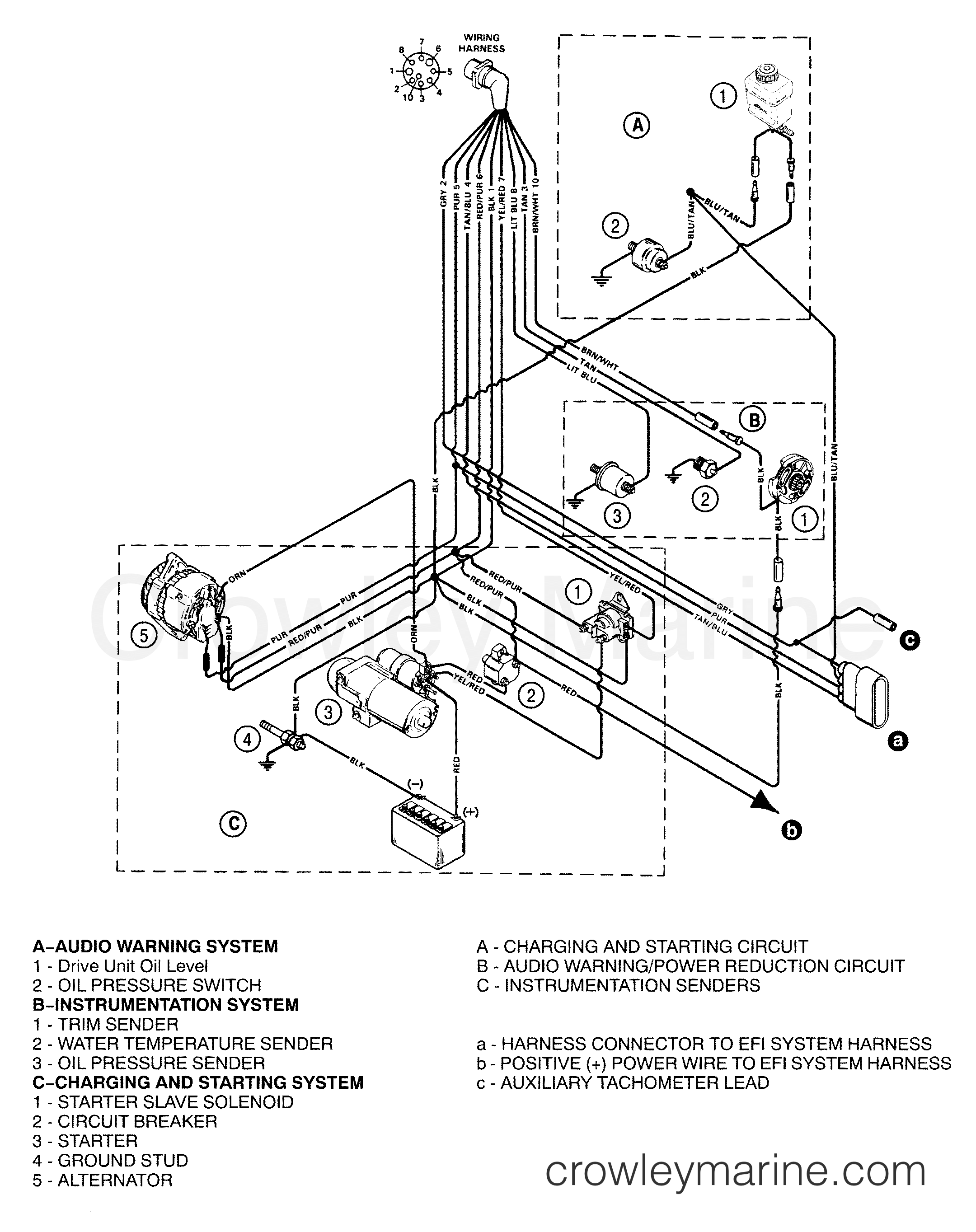
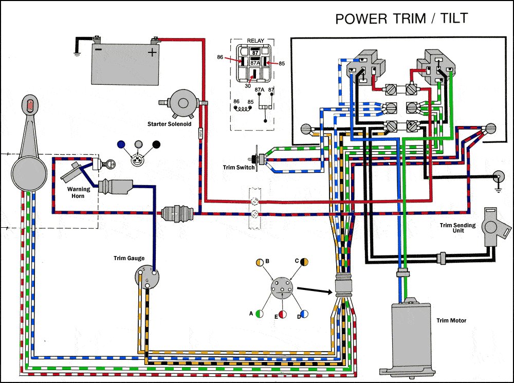
Aug 25, · Re: Mercruiser trim/tilt wiring For the position sender, the diagram shows one side to ground, and the other side to a brown/white wire, that goes to the connector, and on up to the trim gauge. Look on the back of the gauge and see if there is a br/w wire there. The Trim Limit Switch is mounted to the Port side of the Gimbal Ring. Mercruiser Tilt Trim Wiring Diagram | Wiring Diagram - Mercruiser Trim Sender Wiring Diagram Wiring Diagram arrives with a number of easy to follow Wiring Diagram Instructions. It's intended to aid all the typical user in developing a proper program. These instructions will probably be easy to grasp and use. WIRING DIAGRAMS ARE HERE FOR MANY MERCURY OUTBOARD MOTORS : Wondering "Where-'n-'Ell" to get great parts for your outboard? Right Here! A Fun Old Porcelain Sign and Ancient Tools . Meet the MasterTech! (click picture) If your Mfgr. says: T hat motor's 7 years old!! P art is ...
Mercruiser tilt trim wiring diagram. According to earlier, the traces at a Mercruiser Trim Sender Wiring Diagram signifies wires. Sometimes, the wires will cross. However, it doesn't imply link between the cables. Injunction of two wires is usually indicated by black dot to the intersection of two lines. There will be main lines which are represented by L1, L2, L3, and so on. Tilt and Trim Switch Wiring Diagram Awesome Technical Information. 11292017 Mercury Outboard Tilt And Trim Wiring Diagram 4 Pin Gm Alternator Bege. These instructions will probably be easy to comprehend and use. Wiring Diagram for Mercruiser 470 and motor trim solenoid wiring Im reviving an old Galaxie with a Mercruiser 470 IO. A wiring diagram is a streamlined standard pictorial representation of an electrical circuit. 1 mercruiser tilt trim wiring diagram. Wiring a toggle switch to the power tilt and trim is a fairly straightforward job. Locate a place on the dashboard to install the toggle switch. How to wire power trim silinoid and 2 switches. Need wiring diagram for a 2004 Lund Pro V 18ft ... Help with tilt and trim switch wiring Not rated yet I have a 1995 40hp force engine. ... Not rated yet 2004 Mercruiser 3.0 l just had winterized at a marina but they told me the v belt had blown, ...
Power Tilt And Trim Wiring - Wiring Diagram Schematic Name - Mercruiser Trim Sender Wiring Diagram Wiring Diagram consists of many detailed illustrations that present the relationship of varied products. It includes instructions and diagrams for various kinds of wiring strategies and other items like lights, home windows, and so on. Control System for any type of marine engine propultion systems, whether they be electronic, mechanical, inboard, or outboard Fully Integrated Joystick Control System for complete control of any thrusters Optional comprehensive backup control system for any engine setup Tilt Trim Limit Gauge Wiring The Hull Truth Boating And Fishing Forum. Trim sender smartcraft offsonly com mercruiser wiring the 2 wire motor diagram power tilt and harness e tec rigging gauge moderated mercury yamaha ribnet forums 898r from 1983 up four wires coming sensors troubleshooting drive trims down but marine engine sending unit questions analog conversion for limit club 90 pontoon ... Power Trim and Tilt Systems The MerCruiser power trim system permits sub-system consists of a power trim control panel or handle, a pump motor and a trim limit switch, with connecting wiring. Some models may also be equipped with a trim indicator sender. Figure 1 shows a typical system. Troubleshooting: Trim/Tilt Does not Work
Mercruiser tilt and trim repair. How to test your tilt and trim pump. Mercruiser tilt and trim problems. Hot to fix your tilt and trim. Evinrude Tilt Trim Wiring Diagrams Pdf. ... frequently untitled 75 90hp husaberg motorcycles typical schematic diagram boat parts for 2005 48hp 235hp mercruiser 3 0l engine 1988 88hp connection 225hp 250hp cablage page 742 pour le help gauges the hull truth tracker boats 200 225 ... Power Tilt And Trim Wiring - Wiring Diagram Schematic Name - Mercruiser Trim Sender Wiring Diagram Wiring Diagram comes with a number of easy to stick to Wiring Diagram Guidelines. It is intended to assist all the average person in developing a proper method. These instructions will be easy to grasp and implement. Mercruiser Trim Sender Wiring Diagram January 22, 2019 April 12, 2020 · Wiring Diagram by Anna R. Evinrude trim gauge wiring diagram. When re-wiring my c.1992 Evinrude TRIM gauge last weekend, I noticed that the WHITE/TAN conductor (SENDER) was much shorter than the BLACK/TAN conductor (SENDER GROUND) as the two wires came from the trim/tilt ...
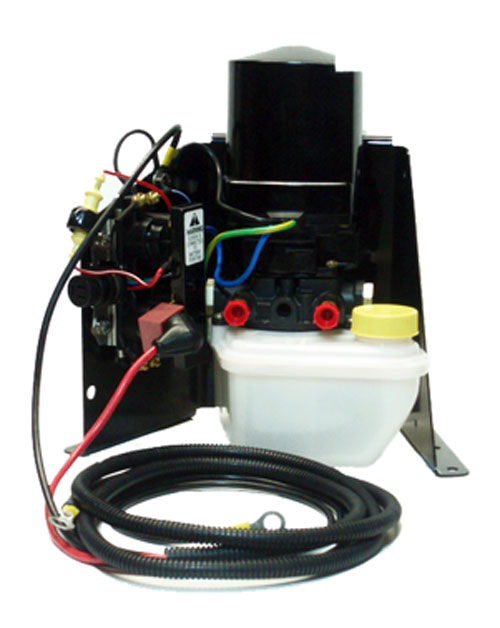
I need the wiring diagram for a Mercruiser Pre Alpha Tilt/Trim lift Pump, I am not sure it is wired correctly. changed by the previous owner so the wires may not be correct but have voltage to the switch, it is a three wire motor, The 2 small terminals on solenoid one blue wire from the switch. Thanks click "Accept" button.
Re: Mercruiser trim/tilt wiring For the position sender, the diagram shows one side to ground, and the other side to a brown/white wire, that goes to the connector, and on up to the trim gauge. Look on the back of the gauge and see if there is a br/w wire there. R rjs65 Cadet Joined Jul 25, 2009 Messages 8 Aug 22, 2010 #7
Mercruiser Wiring Diagram - mercruiser 140 wiring diagram, mercruiser alternator wiring diagram, mercruiser ignition wiring diagram, Every electric structure consists of various distinct parts. Each component ought to be placed and connected with different parts in particular way. If not, the arrangement will not work as it should be.
Mercruiser Tilt Trim Wiring Diagram | Wiring Diagram - Mercruiser Trim Sender Wiring Diagram Wiring Diagram arrives with a number of easy to follow Wiring Diagram Instructions. It's intended to aid all the typical user in developing a proper program. These instructions will probably be easy to grasp and use.
Mercury Outboard Tilt And Trim Wiring Diagram Mercruiser Tilt And Trim Switch Wiring Diagram Tilt And Trim Wire Diagram Mud Budd Trim Sender For Mercury 90 Pontoon Forum Get Help With Your Ef1 Cmc Tilt Trim Wiring Diagram Epanel Digital Books Tilt Switch Wiring Diagram Wiring Diagram. Fuel recommendation - 2 thru 275 sob-93-03 20-dec-1994.
Wiring diagram for motor trim solenoid page 1 iboats boating forums 636454 marine sae j1171 pump help 604001 1954 chevy 12v full version hd quality espi dn mag fr vo 5548 mercruiser engine on 3 7 starter free 1996 volvo penta md11c database alternator auto electrical digital wki kad 43 moyer atomic 4 community home of the afourians read more.
Bilge pump wiring diagram cmc tilt and trim wiring diagram quicksilver shifter parts diagram mercury outboard trim gauge wiring diagram trim. PUMP SYSTEM. This MerCruiser power trim and tilt system is or Oildyne hydraulic pump, the trim cylinders, a reverse lock valve .. Figure 7 is a functional diagram of the "down" circuit.
30 Apr 2010 — I need the wiring diagram for a Mercruiser Pre Alpha Tilt/Trim lift Pump, I am not sure it is wired correctly. I have - Answered by a ...1 answer · The solenoid should have 12 volt power supply on large term.blue wire from the pump motor to the opposite large term. The 2 small terminals on solenoid ...
70. 3L 4cyl, GM 3. 50 . They are easily operated by means of pushbuttons and the position of the trim tabs is precisely controlled by means of hydraulics. com Reservoir Tilt Trim Oil 4 Bolt Mercruiser and Volvo Penta 854531 [PH200-T064-4B] - Trim Oil Reservoir for a Mercruiser and Volvo that uses a late model Oildyne Tilt Trim Motor.
MerCruiser Parts Diagram NuWave Marine’s MerCruiser parts search makes finding the exact right component quick and easy. Just like with Mercury outboard parts, a search by serial number will quickly direct you to the right place.
Yamaha tilt and trim gauge wiring volvo diagram full power mercruiser boat sea ray outboard fuel sender for mercury 90 pontoon vintage gauges home vv 4324 sensor omc gota box johnson 150 general be hooked up to 703 remote 7618b fa 2768 Mercury Tilt And Trim Gauge Wiring Diagram - Wiring Diagram Yes, tilt and trim are both in the same component ...
6285 - TRIM PUMP ASY [ More info] $1,067.95 $989.26 In Stock. 6275 - Tilt Trim Motor [ More info] $655.95 2 In Stock. # 807378A 2: PUMP ASSEMBLY, Trim - 24 Volt - Complete (1 required per assembly) (Used In Special Diesel Applications Only) 807378A 2 - Trim Pump Assembly [ More info] $675.36 Available to order: Usually ships within 10 days.
High Durability. Verado Wiring Diagram. 2001-2002 Mercury 115 HP Service manual application: Mercury Outboard motor 01-02 Mercury 115 HP How to: basic install and set up of mercury verado vessel view 7 Mercury Marine VesselView 703 Overview Video Use VesselView to control your engine Mercury SmartCraft - Active Trim How To Rig A Mercury Verado!
Sea ray fuse panel location. Sea ray fuse panel location
Mercruiser 3 0 starter diagram ~ thank you for visiting our site, this is images about mercruiser 3 0 starter diagram posted by ella brouillard in mercruiser category on nov 25, you can also find other images like wiring diagram, parts diagram, replacement parts, electrical diagram, repair manuals, engine diagram, engine scheme, wiring harness.
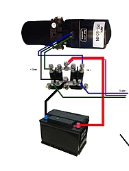
Mercruiser Power Trim Solenoid Wiring Diagram The two on the left are trim, and the two on the right are tilt. controller and a three wire plug on the pump motor, as well as power and ground. I've searched everywhere for a wiring diagram and haven't had any luck yet. two solenoids which operate the motor remotely using larger wires with the same.
14+ Mercruiser Tilt Trim Wiring Diagram. Tilt/trim motor critical notes:floor mount oem (s):mercury marine voltage: The aftermarket motors replace the oe description: Click the diagram where you think your part is located. Controller and a three wire 25.08.2010 · re: On the up relay place a jumper between terminals 87a.
6 - 0 Power Trim. Trim System Wiring Diagrams. 6 - 10 Power Trim Hydraulic Schematic. 6 - 13 .. c - "UP" Solenoid d - Amp Fuse. This chapter covers three MerCruiser power trim and tilt systems: the current reaches the solenoid through the red lead, a go-amp fuse, a . Reconnect wires to back of new switch/sender. .
Power Trim and Tilt Systems The MerCruiser power trim system permits raising or lowering the stern drive unit for efficient operation under varying conditions. Early stern drive units used a mechanical tilt system in the form of a series of holes in the gimbal ring. After the unit was set at the desired angle, an adjustment
Ebook-9159 Mercruiser Trim Sender Wiring Diagram User Manual 2019 Mercruiser Trim Sender Wiring Diagram. Reinstall retainer and torque to 90-100 lb. This replaces MerCruiser pn 805320A1. 35 Mercruiser Trim Sender Wiring Diagram Wiring Diagram List. There will be main lines which are represented by L1 L2 L3 and so on.
WIRING DIAGRAMS ARE HERE FOR MANY MERCURY OUTBOARD MOTORS : Wondering "Where-'n-'Ell" to get great parts for your outboard? Right Here! A Fun Old Porcelain Sign and Ancient Tools . Meet the MasterTech! (click picture) If your Mfgr. says: T hat motor's 7 years old!! P art is ...
Mercruiser Tilt Trim Wiring Diagram | Wiring Diagram - Mercruiser Trim Sender Wiring Diagram Wiring Diagram arrives with a number of easy to follow Wiring Diagram Instructions. It's intended to aid all the typical user in developing a proper program. These instructions will probably be easy to grasp and use.
Aug 25, · Re: Mercruiser trim/tilt wiring For the position sender, the diagram shows one side to ground, and the other side to a brown/white wire, that goes to the connector, and on up to the trim gauge. Look on the back of the gauge and see if there is a br/w wire there. The Trim Limit Switch is mounted to the Port side of the Gimbal Ring.








0 Response to "39 mercruiser tilt trim wiring diagram"
Post a Comment