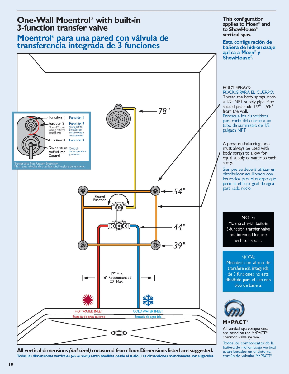
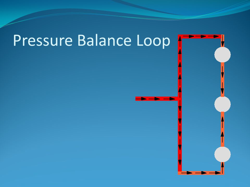
40 pressure balancing loop diagram
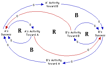
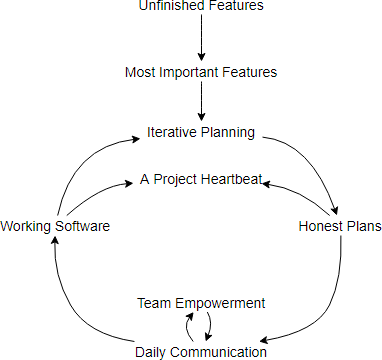
Causal loops diagrams (also known as system thinking diagrams) are used to display the behavior of cause and effect from a system’s standpoint. Fishbone diagrams may elicit the categories of causes that impact a problem. Causal loops show the interrelation causes and their effects. When finished you have a diagram of the positive and negative …
Caleffi North America, Inc. 9850 South 54th Street Franklin, WI 53132 T: 414.421.1000 F: 414.421.2878 Dear Hydronic Professional, Welcome to the 2nd edition of idronics – Caleffi’s semi-annual design journal for hydronic professionals.
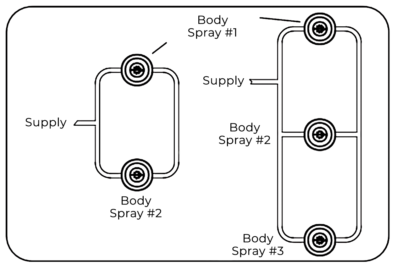
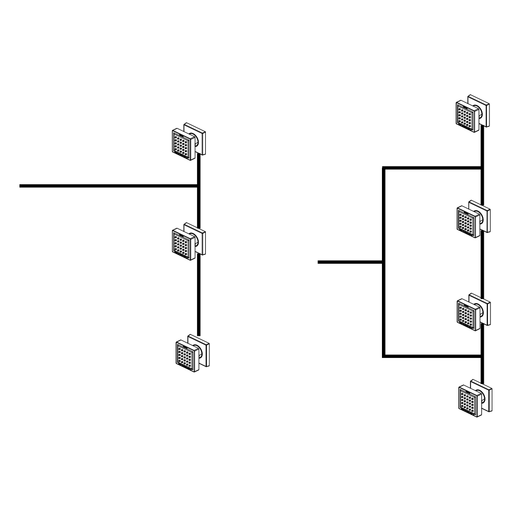
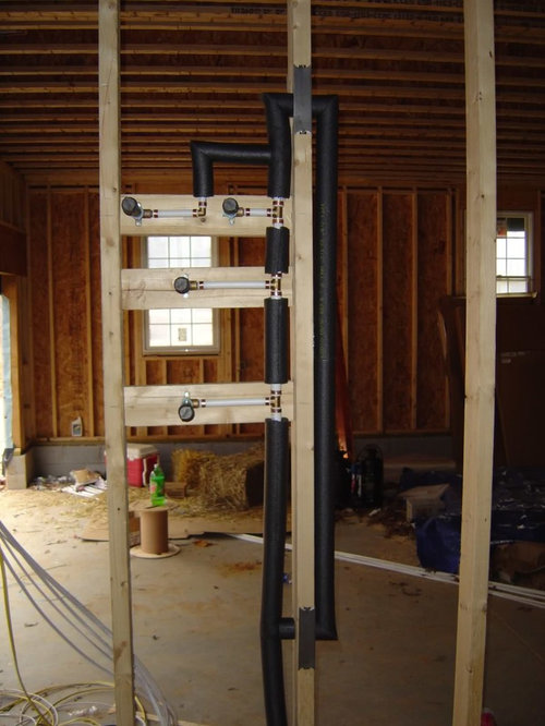
Get a 3/4" shower valve; maybe a big tub valve with pressure balancing or thermostatic control. 2. Come out of the valve into the branch of a tee and make a loop of 3/4" connecting both ends of the tee.

Pressure balancing loop diagram
A term to express pressure drop in a closed loop system • What produces head loss? Friction of the water rubbing against the pipe as it flows through the system. • 1 PSI of pressure drop = 2.31 feet of head • Does height of the building influence head loss? No • Why?It’s a circulator, not a pump. It’s a closed loop system and the ...
“closed” loop is that due to flow-friction pressure drop; static heights are not considered. Figure 1 Static Height (H) Not Considered for Pump Selection in Closed Loop The “open” or tower circuit is different from the “closed” loop circuit. The difference is that all static heads are not cancellable.
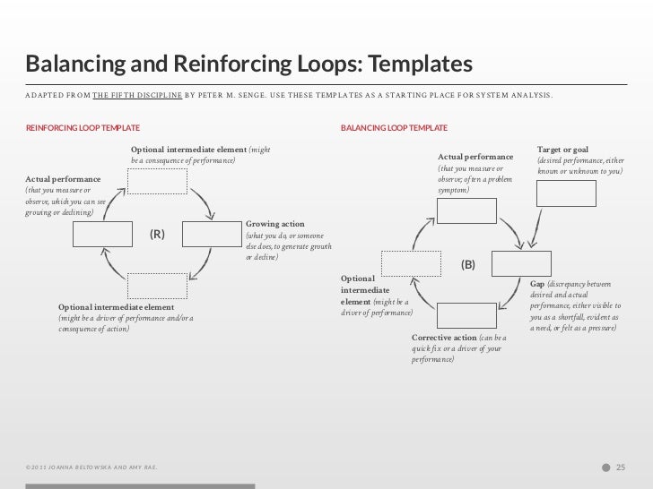
In causal loop diagrams, balancing loops are noted by a “B,” a “—,” or a scale icon in the center of a loop. The Structure of Balancing Loops. There is always an inherent goal in a balancing process, whether it is visible or not. The basic structure of a balancing loop involves a gap between the goal (or desired level) and the actual ...
Pressure balancing loop diagram.
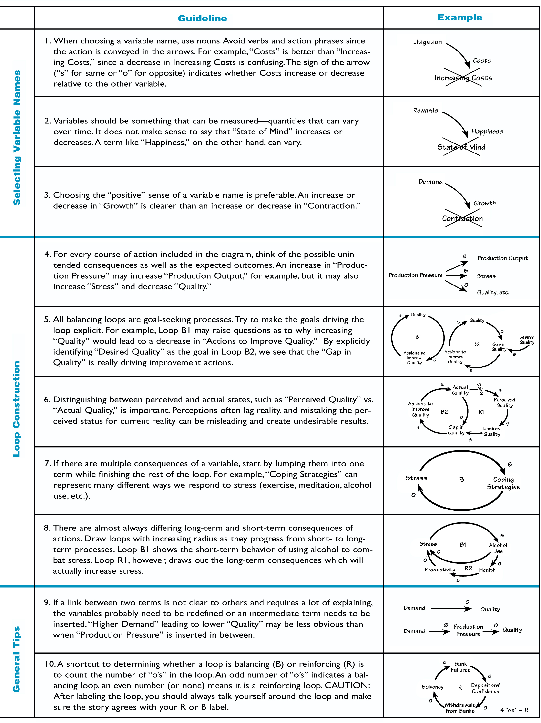
course of action included in the diagram. For example, an increase in “Production Pressure” may increase “Production Output,” but it may also increase “Stress” and decrease “Quality” 5. All balancing loops are goal-seeking processes. Try to make explicit the goals driving the loop.
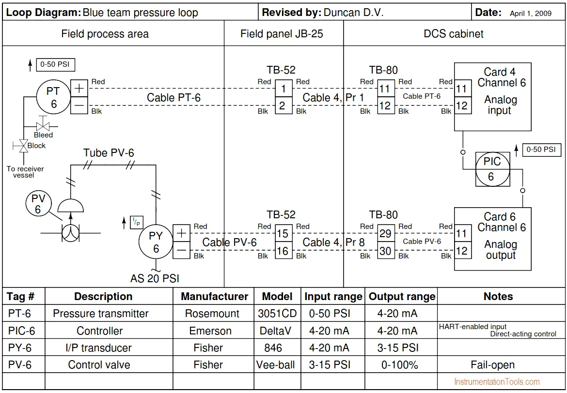
P&IDs AND LOOP DIAGRAMS P&IDs and loop diagrams are construction and documentation drawings that depict the flow of the process and illustrate the instrumentation control and measurement interactions, wiring and connections to the process. The process is illustrated in sections or subsystems of the process called loops. A loop diagram will ...
Pressure Balancing Loops. Jump to Latest Follow 1 - 7 of 7 Posts. D. DDial · Registered. Joined Dec 4, 2017 · 11 Posts . Discussion Starter · #1 · Jan 26, 2018. Only show this user ...
I'm making a pressure balancing loop. Due to piping req'ts, I am unable to position the loop inlet exactly in the middle of the non-fixture side. Is this okay, or do I need to make sure that the pipe distances from the inlet to the first spray (in each direction of the loop) are both exactly the same? Upvote. # 2. 07-27-03, 06:35 PM. bigbluedude2.











0 Response to "40 pressure balancing loop diagram"
Post a Comment