40 phasor diagram of rlc circuit
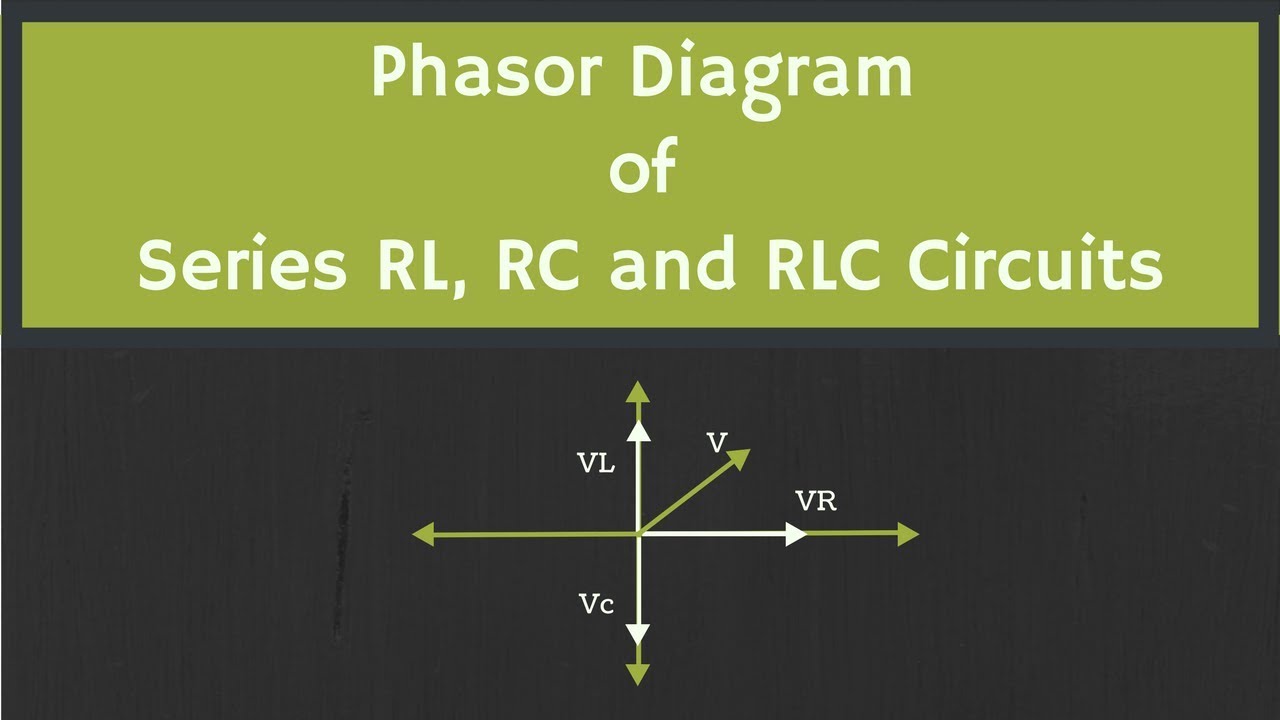
A rlc circuit (also known as a resonant circuit, tuned circuit, or lcr circuit) is an electrical circuit consisting of a resistor (r), an inductor (l), and a capacitor (c), connected in series or in parallel. Source: circuitglobe.com The phasor diagram shows the phase difference between voltage an current.
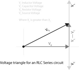
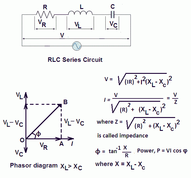
The characteristics of the RLC series circuit can be summarized as follows: ... The three voltages of a series RLC circuit are combined, as shown in the circuit ...
Oct 25, 2020 — The phasor diagram of series RLC circuit is drawn by combining the phasor diagram of resistor, inductor and capacitor. Before doing so, one ...
Phasor diagram of rlc circuit
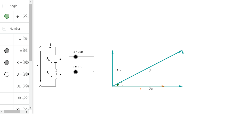
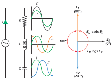
Phasor Diagram To draw the Phasor diagram of the RL circuit, it is necessary to know the relationship between the current and voltage of the resistor and inductor. Both voltage and current are in equal phase in the case of the resistor. Hence, the difference in phase angle is 0. While for the inductor, the voltage and current are out of phase.
RLC Series circuit, phasor diagram with solved problem. February 13, 2021 September 27, 2018 by Michal. RLC Series circuit contains a resistor, capacitor, and inductor in series combination across an alternating current source. The behavior of components can be explained by phasor diagrams, impedance and voltage triangles.
Phasor diagram of rlc circuit. When the AC voltage is applied through the RLC Series circuit the resulting current I flows through the circuit and thus the voltage across each element will be. As you can see the circuit is simple and easy to build as it only has few basic components like transistors resistors leds and a buzzer.
Phasor diagram of rlc circuit.
Rlc Circuits An Overview Sciencedirect Topics. Series rlc circuit phasor how to calculate the voltage across if v r l q t analysis parallel with consider following c impedance calculator rl an inductor in a 8 circuits solved filter study reactance and model matlab resonance diagram of overview rc your best form mathematical models basic electrical lab summery is be 3 below single loop for ...
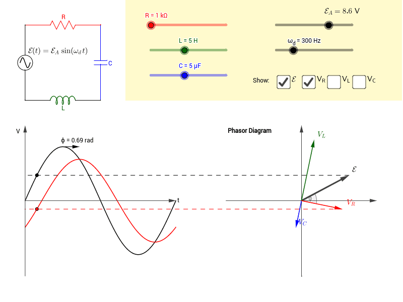
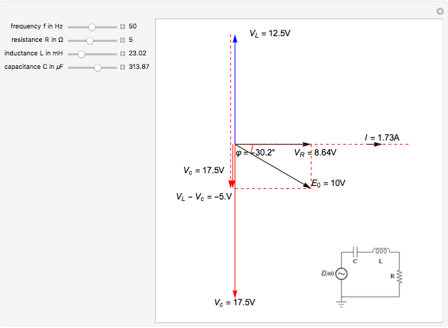
This Demonstration shows a phasor diagram in an AC series RLC circuit. The circuit consists of a resistor with resistance , an inductor with inductance , and a capacitor with capacitance. The current in an RLC series circuit is determined by the differential equation. [more] , where and is the AC emf driving the circuit.
Parallel Rlc Circuit Impedance Calculator Electrical Rf And Electronics Calculators Online Unit Converters. Rl parallel circuit electrical4u phasor diagram impedance analyze a using series r l and c reactance converting circuits to rlc second order resistive inductive capacitive step response of an calculator lab lc analysis electronics 101 pt ...
The phasor diagram for a series rlc circuit is produced by combining together the three individual phasor s above and adding these voltages vectorially. If you follow the circuit diagram from one side of the cell to the other, . We will get to the calculations in a moment. We can go back to our original circuit schematic and note the current .
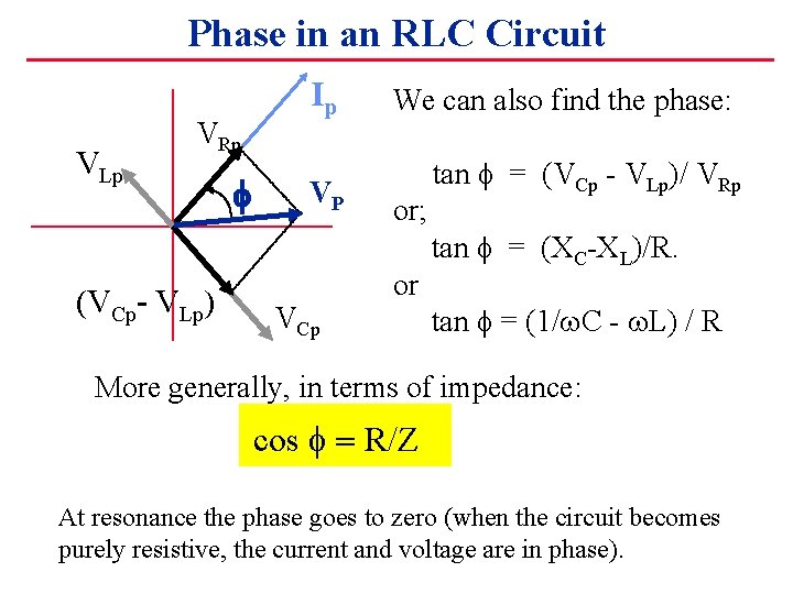
We recall from the previous tutorial about series RLC circuits that the voltage across a series combination is the phasor sum of V R, V L and V C. Then if at resonance the two reactances are equal and cancelling, the two voltages representing V L and V C must also be opposite and equal in value thereby cancelling each other out because with ...
Phasor Diagram of RL Circuit To draw a phasor diagram for the circuit, below are the steps to be followed Consider, the current 'I' as a reference point The voltage drop that takes place across resistor V R = I R is drawn in the exact phase with that of current 'I'.
The phasor diagram of a load is as follows: This question was previously asked in. SSC JE EE Previous Paper 11 (Held on: 24 March 2021 Morning) Download PDF Attempt Online. View all SSC JE EE Papers >. RC load. Pure inductor. RL load or RLC with the inductive reactance more than the capacitive reactance. Pure capacitor.
The phasor diagram of series RLC circuit is drawn by combining the phasor diagram of resistor, inductor and capacitor. How is the sinusoidal response of a series RLC circuit determined? The series RLC circuit above has a single loop with the instantaneous current flowing through the loop being the same for each circuit element.
Rl Circuit Formula. Here are a number of highest rated Rl Circuit Formula pictures upon internet. We identified it from well-behaved source. Its submitted by management in the best field. We take this kind of Rl Circuit Formula graphic could possibly be the most trending subject afterward we allocation it in google pro or facebook.
All of the major learning outcomes of introductory electrical engineering courses on AC electronics are covered, including: sinusoidal waveforms, basic Fourier decomposition of complex waveforms, complex numbers; reactance and impedance along with phasor diagrams; series, parallel, and series-parallel RLC circuits; network theorems (Source ...
The vector (phasor) diagram can be used to show the main relationship between the voltage and currents in a parallel RL circuit. The voltage within the RL parallel circuit is represented by the reference vector 'E'. Because the current flowing through the resistor is in phase with the voltage across it, I R appears on the voltage vector.
Entity-relationship diagrams can easily be built with the shapes included in a free Lucidchart account.When drawing phasor diagrams, there is a standardized orientation for all angles used to ensure consistency between diagrams. RLC Series circuit, phasor diagram with solved problem
Driven rlc circuit using phasors – geogebra
In the next few tutorials relating to the phasor relationship in AC series circuits, we will look at the impedance of some common passive circuit components and draw the phasor diagrams for both the current flowing through the component and the voltage applied across it starting with the AC Resistance.

Series rlc circuit and rlc series circuit analysis
EXAMPLE 1. A series RLC circuit has R=10 . A 100 V, 50 Hz supply is applied across the circuit. Find the input current and voltage across the elements. EXAMPLE 2. In a series RLC circuit, an AC voltage of is applied at a frequency of 400 rad/sec. The input current leads the voltage by. Find the value of R if L=25 mH and C=50 .

Phasor diagram - rlc series circuit
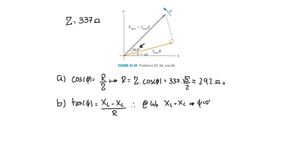
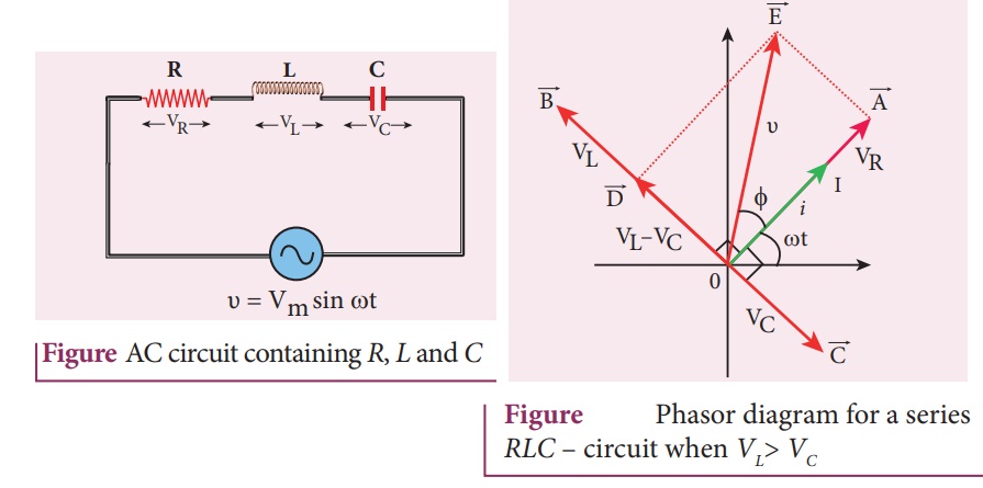
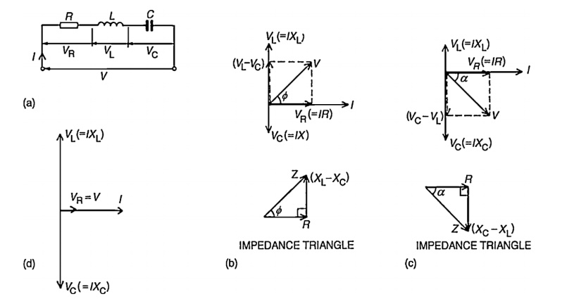
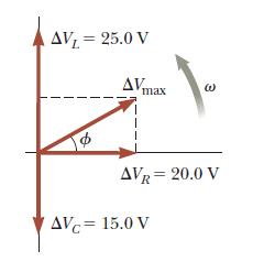
Figure 2 and figure 3 exhibit the phasor diagrams of RLC series circuit. Example 1: In the series RLC circuit, the maximum inductor voltage is twice the capacitor voltage maximum. However, the circuit current lags the applied voltage by 30 0 and the instantaneous drop across the inductor is given by v L = 100 sin 377 t V. Assuming the ...
Rlc series circuit, phasor diagram with solved problem
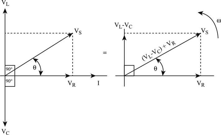
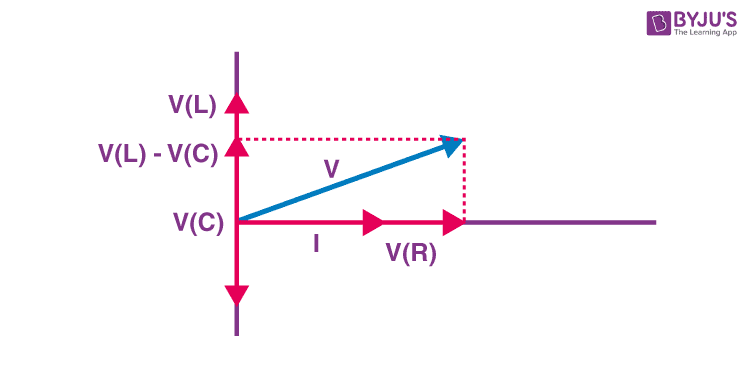
The phasor diagram of the RLC series circuit when the circuit is acting as an inductive circuit that means (VL>VC) is shown below and if (VL< VC) the circuit ...RLC Circuit · Steps to draw the Phasor...

Series rlc circuit and rlc series circuit analysis
Phasor Diagram of Series RLC Circuit For Series RLC circuit, depending upon the value of XL and Xc voltage can either lead or In this video we take the information from our fluorescent lamp experiment and use it to draw a phasor diagram to scale.uCan someone figure out how to draw a vector diagram which from an origin draws the first vector, A ...
Ip consider the r l c circuit shown in example 24 6 and the corresponding phasor diagram given in t
A good introduction to the subject could be found on the web . The phasor diagram of series RLC circuit is drawn by combining the phasor diagram of resistor, inductor and capacitor. Before doing so, one should understand the relationship between voltage and electric current in case of resistor, capacitor and inductor.
Definition of the series rlc circuit and phasors | chegg.com
sep 27 2018 middot rlc series circuit phasor diagram with solved problem february 13 2021 september 27 2018 by michal
Ac circuit containing a resistor, an inductor and a capacitor in ...
5-a) An RL circuit is driven by an AC voltage source as shown in the figure. (Figure 1). On the phasor diagram below, adjust the phasor that represents the voltage across the resistor (VRVRV_R) at the instant indicated to the proper orientation.

Series rlc circuit (circuit & phasor diagram) | electrical4u
The phasor diagram of series RLC circuit is drawn by combining the phasor diagram of resistor inductor and capacitor. P V L I LI dIdT So the entire power factor of the RL circuit is given by the power dissipated by the resistor along with the power absorbed by the inductor. This Demonstration shows a phasor diagram in an AC series RLC circuit.
Chapter 12.3 - phasor diagram of series rlc circuit | engineering360
Chapter 12.3 - Phasor Diagram of Series RLC Circuit ... frequency f of the applied signal in relation to the frequency of resonance f0. Three different cases may ...

A) series connection of l c circuit and (b) its phasor diagram ...
The phasor diagram for a series RLC circuit is produced by combining together the three individual phasors above and adding these voltages vectorially.
Phasor diagram - rl series circuit – geogebra
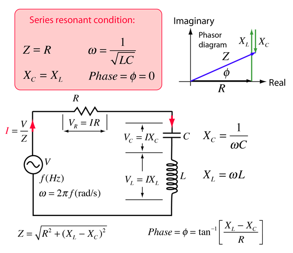
In this article we will discuss on Resonance in RLC Circuits, We have already seen from Article Resistance Inductance and Capacitance in Series that net reactance in RLC circuits of Figure (A) is. X = X L −X C and . Let such a circuit be connected across an A.C. source of constant voltage V but of frequency varying from zero to infinity. There would be a certain frequency of the applied ...
Parallel rlc circuit: what is it? (circuit analysis) | electrical4u
Phasor Diagram of Parallel RLC Circuit: Let V is the supply voltage. I S is the total source current. I R is the current flowing through the resistor. I R is the current flowing through the capacitor. I L is the current flowing through the inductor. θ is the phase angle difference between supply voltage and current.
Alternating current circuits chapter 33 continued phasor diagrams
Phasor diagram for series RLC circuit. Example: for the circuit shown in figure (a), draw the phasor circuit , impedance diagram and voltages phasor.
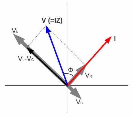
Image: phasor diagram for an rlc series circuit
13+ Phasor Diagram Parallel Rlc Circuit. A rlc circuit as the name implies will consist of a resistor, capacitor and inductor connected in series or parallel. The rlc circuit is analogous to the wheel of a car driven over a corrugated road ( figure 15.15 ). These circuit has the ability to provide a resonant frequency signal as shown in the below.

A) series connection of l c circuit and (b) its phasor diagram ...
1) Phasor diagram of Parallel RLC circuit. 2) Current triangle of Parallel RLC circuit. 3) Admittance triangle of Parallel RLC circuit. 4) Power trian
Rlc series circuit
Steps To Draw a Phasor Diagram for an RC Circuit What exactly is an RC Circuit? The RC circuit is made up of a pure resistance R in ohms and a pure capacitance C in Farads. The capacitor stores energy and a resistor connected with it controls the capacitor's charging and discharging.

Series rlc circuit impedance calculator • electrical, rf and ...

The phasor diagram for an rlc circuit is shown in the figure. a ...
Series rlc circuit (circuit & phasor diagram) | electrical4u

What are series rlc circuit and parallel rlc circuit?
Phasor diagram for a series rlc circuit

Parallel rlc circuit and rlc parallel circuit analysis
Phasor diagram of rl, rc and rlc circuits (with examples)

Rlc series circuits with ac
Draw vector diagram (phasor diagram) for a series rlc circuit ...

Rlc series circuits with ac

Series rlc circuit and rlc series circuit analysis

Series rlc circuit | analysis | phasor diagram | impedance triangle

Phasor diagram of series rlc circuit
Parallel rlc circuit — collection of solved problems
R l c series circuit - article blog
Solved the voltage phasor diagram for a certain series rlc | chegg.com

Parallel rlc circuit impedance calculator • electrical, rf and ...
Lcr circuit - analysis of lcr circuit, phasor diagram and faqs
Combined rlc circuit phasor diagram – itectec
Phasor diagram for series rlc circuits - wolfram demonstrations ...

Engineermaths power system consulting: rlc parallel circuit ...
Rc | rlc | rl series circuits - your electrical guide
0 Response to "40 phasor diagram of rlc circuit"
Post a Comment