40 copeland compressor wiring diagram
compressor or the Copeland Discus Digital ... routing for compressor power wiring will be easier in this position). The maximum wire terminal screw torque is 7 in. lbs. The Digital Compressor Controller will operate in any mounting orientation where the green POWER LED is at the top. Mount the Digital
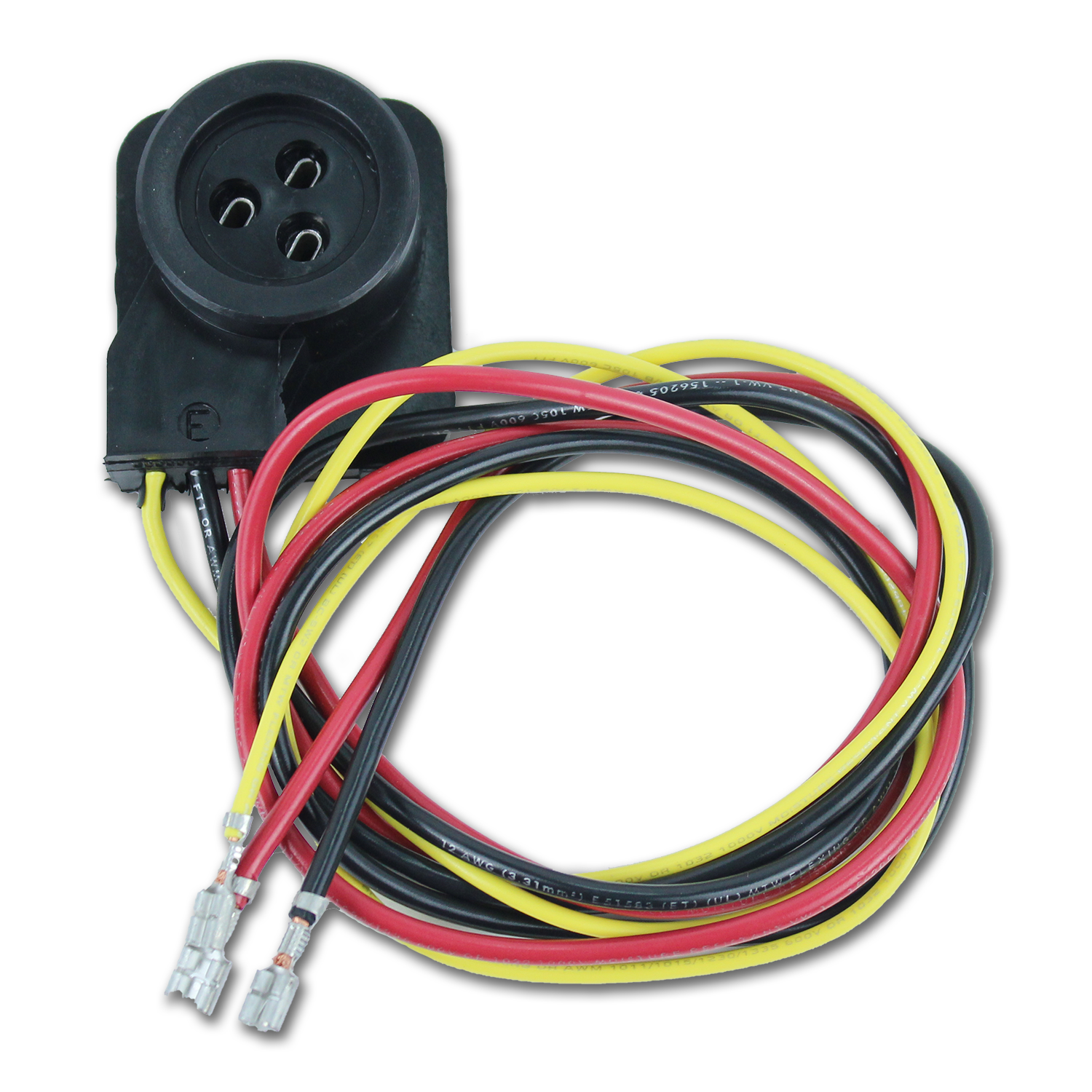
The compressor terminal box has a wiring diagram on the inside of its cover. Before connecting the. Refer to original equipment wiring diagrams. Care must be taken to ensure that wiring or . The Copeland Scroll compressor's inherent.Find best value and selection for your Copeland SCROLL Compressor Wire Harness Connector search on eBay.
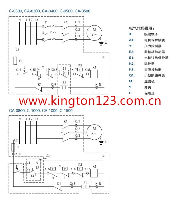
and activates the Copeland Digital 3-cylinder semi-hermetic solenoid valve. An input allows to monitor the discharge temperature or the compressor DLT signal and to send an alarm signal if the specified temperature is exceeded. Figure 10: Wiring diagram for EC3-D13 Driver An ECD-002 display module is available as an option; it displays
Copeland compressor wiring diagram
Copeland® Brand to Copeland® Brand 1 Bristol to Copeland® Brand 6 Tecumseh to Copeland® Brand 9 General Notes 13 Compressor Data Notes, Rating Points 14 ZB, ZF, and ZS Models 15 ZR Models 27 ZFH Models 59 ZP Models 61 ZRT/ZZ Tandem Models 62 Electrical Diagrams 65 Standard Compressor Drawings 66 Electrical Components 79
compressors. DWM Copeland™ compressors are suitable for a wide range of applications either in the form of single compressors, condensing units or as multi-compressor equipment. The compressor is only one component which must be combined with many others to build a functional and efficient refrigeration system.
Wiring Diagrams Contact Us Technical Information User Options Reset Registration ZR42K3-PFV Copeland Mobile Copeland™ Mobile App (July 31, 2014) The Copeland Mobile smartphone app provides on-the-go access to Emerson Climate Technologies Online Product Information (OPI) database for Copeland compressor specifi cations. This database
Copeland compressor wiring diagram.
4 copeland semi hermetic compressor product catalogue feb 2010 by andrew tan lee issuu motors for compressors emerson electronics stream installation guide manuals technical information china scroll wiring diagram zr125kc e tf5 522 manual zr bush of coowor com como vestir a los 50 años hombres get 42 ac csr manualzz 4mf 13x application manuallines pdf manualslib electrical… Read More »
Copeland Potential Relay Wiring Diagram. Know your potential starting relays achr news 10 3 4 solid state and devices 5 motor bearings 6 drives components for electric motors what happened to terminal hvac p m relay model pm a3c2 air conditioning spare parts suppliers wholers in dubai electrical handbook good evil the hard start school basic ...
An A-1 Compressor Technical Video for servoce technicians on "How To" wire a Copeland 9 Lead 230 volt single contact compressor Call us at 800 743-6009...
Copeland Scroll compressors equipped with CoreSense Communications will have an " E" in the electrical code. An example is the 40-ton scroll, ZP485KCE-TED. Module Part Numbers OEM and service compressors will have the CoreSense Communications module installed in the compressor electrical box. Individually packaged modules are
The information and ideas that were elaborated above ought to be a great kick start, though. Aircon Compressor Wiring Diagram. Copeland Scroll Compressor Wiring Diagram Air Conditioner With 18 0 - Aircon Compressor Wiring Diagram Uploaded by Hadir on Sunday, February 17th, 2019 in category Wiring Diagram.
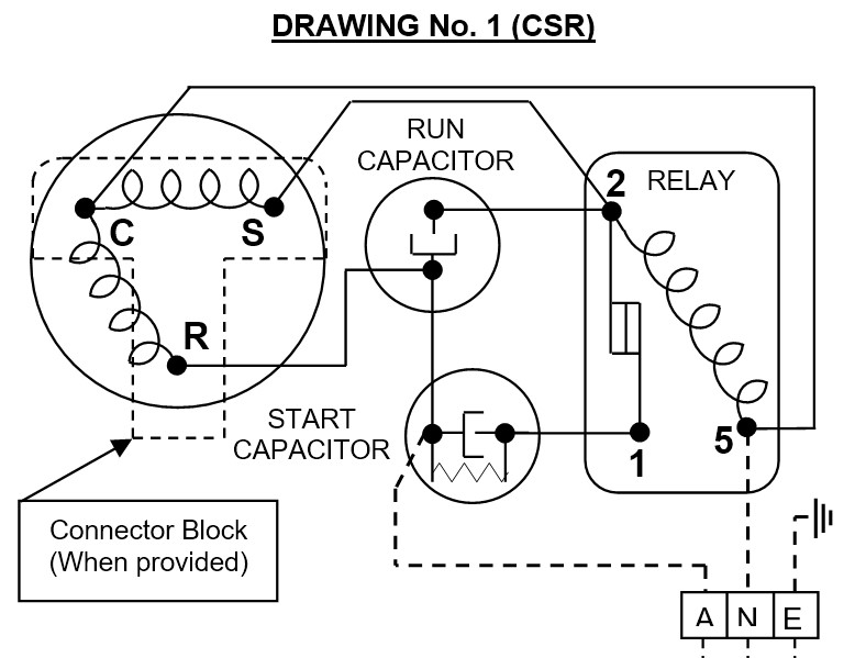
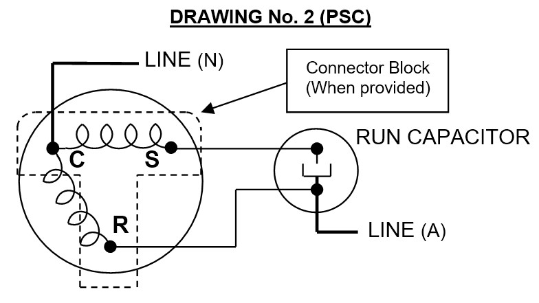
Single-phase compressors (Fig.1) are connected to the common (C), start (S) and run (R) connections. Fusite connections are marked as in figure 1 (single-phase) and figure 2 (three-phase). Recommended wiring diagrams are shown in figures 4 and 5. Fig. 3 Legend (to Fig 3.) 1 Motor 6 Power supply
Table 3: Single-phase compressor models 6 Three-phase motors All DWM Copeland three-phase compressors can be started Direct-On-Line (DOL). The positions of the bridges for Direct-On-Line start depending on type of motor and/or mains voltage are shown on the wiring diagrams. 6.1 Three-phase motor (Star-Delta (Y/∆)): motor code E
Copeland Compressor Wiring Diagram Gallery. copeland compressor wiring diagram - A Newbie s Guide to Circuit Diagrams A very first look at a circuit layout may be complex, yet if you could review a train map, you could review schematics. The objective is the very same: getting from point A to aim B. Literally, a…
Bay Area Air Conditioning & Heating recommends Carrier Infinity Greenspeed intelligence heat pump systems which feature the Copeland Scroll variable speed compressor, enabling increased comfort and year-round savings. In the U.S., large hotels spend an annual average per square foot of $1.05 on electricity and $0.25 on natural gas.
4 5 Safety Information • Copeland™ brand products semi-hermetic compressors are manufactured according to the latest European safety standards. Particular emphasis has been placed on the user's safety. • These compressors are intended for installation in systems according to the EC Machines directive. They may be put to service only if they have been installed in these systems ...
Copeland Compressor Wiring Diagram. accordance with the position of the capacitors and relay shown on the wiring diagram. Compressor model. Run capacitor. Start capacitor. Potential relay. MISWIRING IS MURDER. It is very easy to miswire a compressor, but the results can be deadly. The purpose of this booklet is to dem- onstrate how to wire a.
An A-1 Compressor Technical Video for refrigeration technicians on How To wire a single phase Copeland K Model compressor.. Call us at 800 743-6009 ffor ...
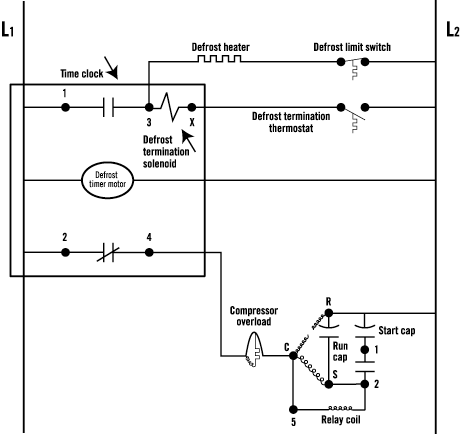
copeland compressor wiring diagram - What's Wiring Diagram? A wiring diagram is a type of schematic which uses abstract pictorial symbols to show all the interconnections of components in the system. Wiring diagrams are made up of a pair of things: symbols that represent the ingredients inside circuit, and lines that represent the ...
Potential Relay Wiring Diagram - compressor potential relay wiring diagram, copeland potential relay wiring diagram, mars potential relay wiring diagram, Every electrical arrangement consists of various distinct components. Each part should be set and connected with different parts in particular way. If not, the structure won't function as it should be.
There are many Air Conditioning and Heat Pump brands in the market but one common component is the compressor. Most use the Copeland Compressor which usually...
The compressor terminal box has a wiring diagram on the inside of its cover. Before connecting the compressor, ensure the supply voltage, the phases and the frequency match the nameplate data. Single-phase compressors are connected to the Common (C), Start (S) and Run (R) connections. Three-phase compressors are connected to
SErVICING COPELaND® BraND COMPrESSOrS ... must coincide with the compressor nameplate. All wiring should be carefully checked against the manufacturer's diagrams. Field wiring must be connected in accordance with the National Electric Code, or other local codes that may apply.
China Copeland Scroll Compressor Wiring Diagram Zr125kc E Tf5 522 Manual Zr. Lg Scroll Compressors Totaline Available Through S Centers 3 Compressor Part Numbering System Label Pdf Doent. Emerson Cr22k6me Pf1 111dm Copeland Crk6 Kq Compressor For Air Conditioning Refrigeration Compressors Semi Hermetic क पल ड प र सर Climate ...
D7.21.01/0806-0108/E 5/27 Technical Information 2.2.3 D8SK - 7000 Diagram 2B Suction gas temperature 25°C 2.3 Selection of Capacity Control D4S - D8S R 407C (mid-point) Compressor
Wiring Diagram For Copeland Compressor. Emerson cr22k6me pf1 111dm copeland crk6 kq compressor for air conditioning refrigeration compressors semi hermetic क पल ड प र सर climate technologies india limited pune id 19774294712 single phase wire diagrams technical information condition electrical engineering centre motors china ...
Compressor wiring diagram. A wiring diagram is a simplified traditional photographic depiction of an electric circuit. The standard 220 volt wiring for an air compressor includes no polarity for the red and the black wire so you cannot wire them backwards. The disconnect switch should be a 220 volt 2 pole type for both circuit wires.
copeland compressor wiring diagram - What's Wiring Diagram? A wiring diagram is a type of schematic which uses abstract pictorial symbols to show all the interconnections of components in the system.
Compressor Wiring Diagram NE-T-J Series - CSR BOX. HomeDiagramsAir conditioner C.S.R wiring diagram compressor start full wiring. November 19, Air conditioner C.S.R wiring diagram compressor start full. While wiring a compressor, there are a number of things to consider for a proper electrical hook up.
















0 Response to "40 copeland compressor wiring diagram"
Post a Comment