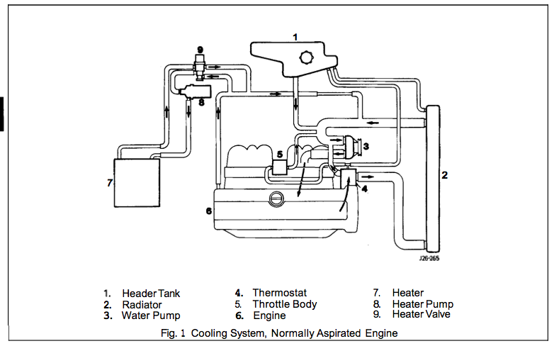
37 lt1 cooling system diagram
The Torque Angle Meter is one tool that not everyone has in their toolbox. Engine Torque Specifications. com. 7L 350Cid LT1 Torque Specifications (Rear Axle System Specific) Fastener Torque Specifications for GM 5. 7 sec 1/4 mile for ea is the same: 14. 691 da 3500 Aug 30, 2009 · Aug 30, 2009. 542 1/4 121. Power Steering System Component View; Camaro Front End Sheet Metal; Z28 Front Bumper Exploded View; Z28 Rear Bumper Exploded View; Wiper Motor and Linkage Exploded View; 1994-1996 Z28 Console Exploded View; HVAC System Vacuum; Radiator Exploded View; Radiator Mounting Exploded View; Radiator Hoses 1993-1994 Exploded View; Heater Hoses 1993-1994 ...
The entire cooling system on the LT1 is designed to operate at lower pressures than conventional cooling systems. The maximum operating pressure in the LT1 cooling system is 15 psi for B/D-cars and 18 psi for F-cars, limited by a pressure cap. These limits are similar to other cars, but in the LT1, these maximum pressures are rarely reached.
Lt1 cooling system diagram
Cooling Fans Schematic; Manual Fan Switch Connection Location; Manual Fan Switch Diagram OBD-I; Manual Fan Switch Diagram OBD-II; Transmission Performance Button Diagram; Optispark Plug Wire Locations & Firing Order; Distributor Ignition System Schematic (1993) Distributor Ignition System Schematic (1994-1995) Distributor Ignition System ... - MINI GEN II HC WIRING DIAGRAM - MINI GEN II HCD WIRING DIAGRAM - 11086-VUS/11076-VUS Trinary Switch Wiring Diagram for Ford or GM PCM with Power Lead for Engine Cooling Fan - 11086-VUS/11076-VUS Trinary Switch Wiring Diagram for Dakota Digital PAC 2750 - 11086-VUS/11076-VUS Trinary Switch Wiring Diagram for Derale 16795 PWM Fan Controller LT1 POWER MODULE WIRING DIAGRAM AND INSRUCTIONS Thank you for purchasing our product. We do everything we can to provide you with the most current and up to date diagrams. Please verify pin locations in these diagrams carefully and if they are incorrect email me at pmcmahon@nethere.net Ability to use a Digital meter is a must.
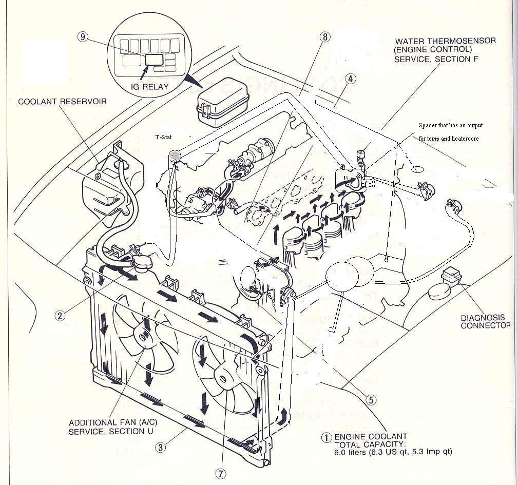
Lt1 cooling system diagram. speaking of the cooling systems sensors. There are three sensors in the LT1 Cooling system: 1. Engine Coolant Level Sensor. This sensor only sends a signal to the light on the instrument panel to illuminate the low coolant indicator lamp. Below is a picture of where this sensor is located. This is a picture of the front of The Chevrolet LT1 5.7L V8 engine that was produced from 1992 to 1997 has some significant differences compared to the previous small block Chevy it replaced, and the third generation LS1 small block that later replaced it. The most obvious difference that distinguishes the LT1 from these other engines is the front-mounted Opti-Spark ignition system. Product Description: Coolant Crossover Line, 93-97 LT1 Camaro, Firebird & 95-96 Impala/Caprice. This is an exact reproduction of the coolant crossover pipes used on LT1 engines from 1993 to 1997 Camaro , 93-97 Firebird 95-96 Impala/Caprice. This pipe mounts on the back of the engine at the top and has been known to go bad over time due to ... Lt1 fuel system limits
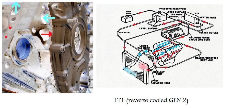
OEM GM Parts Online ships genuine GM parts and accessories nationwide. 4th Gen LT1 F-Body Technical Aids Diagrams Drawings Exploded Views ~For 1995 F-body unless otherwise noted~ (pre 1996) EVAP 1993-1995 Exploded View; EVAP 1996-1997 Exploded View; A/C System Exploded View Brake Pipes and Hoses (non-TCS) Front Brake Dont forget the brake line ... best way i know how and was showed LT1 Reverse Flow Cooling SystemOn my 1995 Chevy Camaro Z28 With the LT1Some basic info about the LT1 Reverse Flow Cooling System.Also:LT1 uses different head... LT1 Reverse Flow Cooling System By Scott Mueller. One of the greatest features of the '92 and up Chevrolet LT1 engine is the reverse flow cooling system. In fact it is reverse flow cooling that is truly the key to the incredible performance of the modern LT1. Mar 13, · C4 Tech/Performance - I need LT1 reverse flow diagrams/pictures of the ...
May 23, 2017 — ... LT1 engine in a street rod with standard aluminum radiator ie only one hose at top and one at bottom. Anyone have a diagram to show how ...Need coolant hose diagram - CamaroZ28.Com Message BoardApr 19, 2017No coolant flow LT1 - CamaroZ28.Com Message BoardJul 10, 201894 lt1 "T" coolant line and how to get rid of it. - CamaroZ28.comJul 19, 200994 LT1 Cooling system diagram - CamaroZ28.comJan 14, 2015More results from www.camaroz28.com In 1992, GM introduced the LT1 engine, a revolutionary new 350 CI small block to be used in all its rear wheel drive vehicles. All of these engines from 1992 through 1997 use a reverse flow water pump that is driven directly off the camshaft. I would sure like to see a clearer diagram. You are right, as usual. about the hose restrictor. Specifically, the 92 Corvette LT1 uses an inline hose restrictor. part# 10157988 Stock TPI and TBI have a restrictor also. Everco part# 4894 V8 S-10 trucks can lower their coolant temps by 10 dgegrees or better using a restrictor too. Lt1 Water Pump Hose Diagram. are three small hose fittings and two large ones on the LT1 water pump. By now have you found a link to a complete hose diagram that I. I'm trying to plumb in the coolant system, anyone have a diagram of where all these I have hoses that go to the intake, heads, water pump. I. The LT1 has no hoses on it and the 37 ...
cooling system diagram - Camaro Forums - Chevy Camaro Enthusiast Forum
May 14, 2020 — Chevrolet's LT1 V-8 was a major step forward for General Motors. From 1992 to 1997, the LT1 helped pull GM ... LT1 Cooling System Diagram ...

Enjoying the Cool in a Garden (c. 1788/90) // Kitagawa Utamaro 喜多川 歌麿 Japanese, 1753 (?)-1806
Jul 20, 2012 — LTX and LSX - LT1 swap radiator hose questions (with diagram for future reference) - I've looked up some answers on how to route the hoses ...
Oil filter mount | Camaro Forums at Z28.com
Sep 11 The Chevrolet LT1 L V8 engine that was produced from to reverse-flow cooling system and mass airflow sequential fuelLT1. The seller provides a color picture of the hoses installed on a LT1 and each hose is numbered. Chevy 350 Lt1 Engine Diagram Lt1 Vacuum Hose Diagram Lt1. 1996 Corvette Lt1 Engine Diagram Wiring Diagram.

EDGE
Chevy 350 Engine Cooling System Diagram Wiring Diagrams Explo Chevy 350 Lt1 Engine Diagram Wiring Diagram Schema Blog Big Block Chevy Water Pump Bypass Hose Option Youtube Heater Core Flushing 1994 Chevy Caprice Lt1 L99 Diy Wagon 350 V8 Engine Coolant Flow Diagram North Star Engine Coolant System Diagram ...
Ls3 Engine Coolant Flow Diagram - Wiring Diagram Schemas
Lt1 reverse flow cooling system diagram Conventional cooling systems have passages in the intake manifold which allow coolant to crossover from one side of the engine to the other. In the LT1, coolant crossover occurs in the water pump, which is also where the thermostat is located.
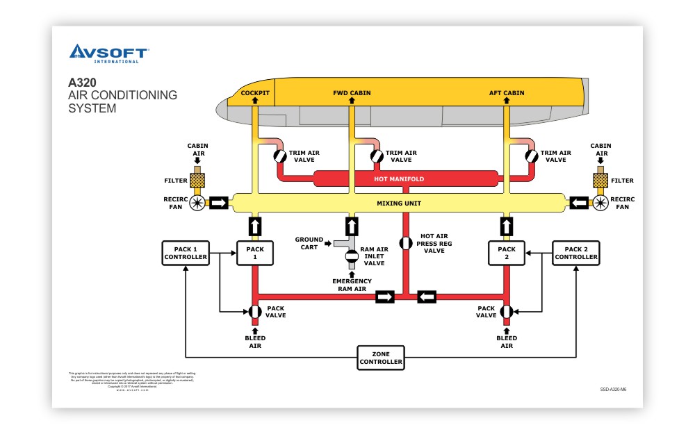
A320 System Diagrams Poster | Airbus A320 Systems Diagrams ...
12/04/2019 · John deere 48 inch mower deck belt diagram. John deere model 48 mower deck 48 inch deck parts fits john deere models 425 445 and 455 series1993 model sn m048hda010001 025000 1994 model sn m048hda025001 040000 1995 model sn m048hda040001 060000 1996 model sn m048hda060001 080000 19.
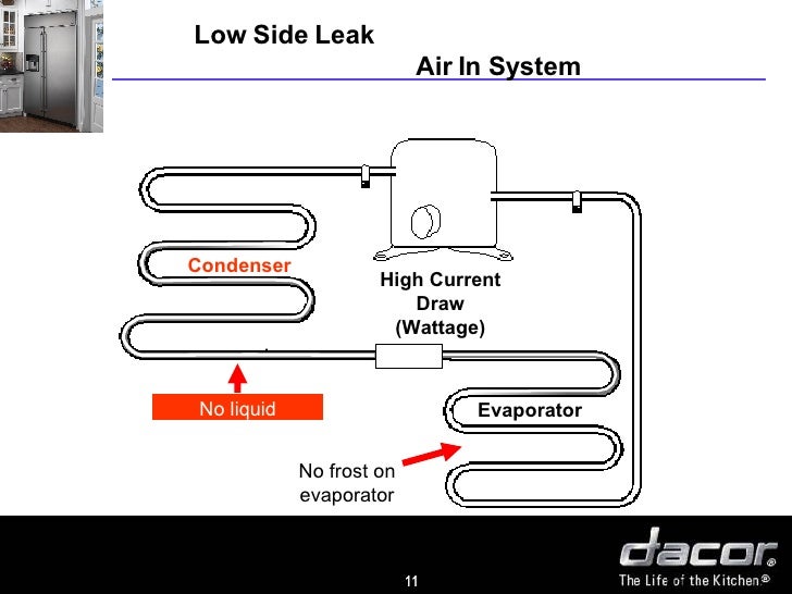
Sealedsystemtest
There are three sensors in the LT1 Cooling system: 1. To pull this off, the Map, IAC, TPS, and ECU temp sensor wires all needed to be extended to fit the LT1 intake manifold layout. So the other day i was poking around my engine bay and noticed that my Air temp sensor wasnt tapped into the 3 inch intake pipe with a LT1 MAF (with translator).
Cooling system hoses - Jaguar Forums - Jaguar Enthusiasts ...
The entire cooling system on the LT1 is designed to operate at lower pressures than conventional cooling systems. The maximum operating pressure in the LT1 cooling system is 15 psi for B/D-cars and 18 psi for F-cars, limited by a pressure cap. These limits are similar to other cars, but in the LT1, these maximum pressures are rarely reached.
Reverse Flow Cooling System - LT1 Z28 Camaro - YouTube
Bleeding the Cooling System on an LT1. Written by Charles O'Toole. Overheating is systemic to these cars when they have not been serviced correctly. If overheating, dumping coolant, etc. are problems after a coolant change or water pump replacement, follow these steps and see if that solves the problem. You willl need 50/50 mix of water and ...
BillaVista.com - ATV Tech Article by BillaVista
Lt1 vacuum hose diagram as well as need help lt1 water pump in addition 94 lt1 engine diagram in addition lt1 cooling fan wiring along with symptoms of bad intake air temperature iat sensor moreover chevy silverado cooling system diagram moreover overhead valve as well as airconditioningservice as well as keeping larry dixons lt4 powered nova ...

cooked food served on platter with ginger and lemon
05/10/2018 · Hi all! I have done a lot of research and work on the cooling system for my 1985 Corvette. I have modified the controls for the cooling system and the engine. Sent the engine to the machine shop for a complete rebuild. New aluminum radiator (suppose to cool up to 800hp), water pump, hoses, 15lb cap and reverted it back to carburetor (Holley 600).
Silver Top Zetec Water Route
Mar 12, 2007 — LT1 Coolant Flow: The LT1 is completely different since it uses reverse flow cooling. The incoming coolant first encounters the thermostat, ...Coolant flow diagram - CorvetteForumJan 7, 2011Please help with HEATER HOSE routing -96 LT1 - Corvette ...Jun 23, 2014I need some hose routing information regarding 93 through 96 ...May 22, 200294 heater hose diagram - CorvetteForumOct 18, 2011More results from www.corvetteforum.com

System Diagram Exercise - Part 1 - Plant Tour v1 - YouTube
20/11/2021 · Lt1 pcm reset. Does the 1995 lt1 350 Camaro have forged pistons? forged pistons or no in a lti 1995 camaro. For students in grades K-5, passwords are in a fixed format and will not be reset. 0L or 5. Chevy 350 Engine Specs The Chevy 350 engine is a 350 cubic inch (5.

Club de Centre Rural: Perspective Sketch (1943) // Le Corbusier French, born Switzerland, 1887-1965
Coolant is drawn from the radiator outlet and into the water pump inlet by the water pump. Some coolant will then be pumped from the water pump, to the heater core, then back to the water pump. This provides the passenger compartment with heat and defrost. Coolant is also pumped through the water pump outlet and into the engine block.
coolant flow question - Miata Turbo Forum - Boost cars ...
The bigger, the better.. However a 144 square-inch surface area is a good size, 1" thick. If you track the vehicle, you may want to go bigger and/or put an aux fan on it. On the LT engines, there is a hole in the block after you remove your oil cooler (coolant passage), and also a nipple on the bottom of the water pump that will need a cap.

860-880 North Lake Shore Drive, Electrical Riser Diagram (11/28/1949) // Ludwig Mies van der Rohe (American, born Germany, 1886–1969) Associate Architect: Holsman, Holsman, Klekamp and Taylor (American, 20th century) Associate Architect: Pace Associates (American, 20th century) Structural Engineer: Frank J. Kornacker (American, active 1940s–1950s)
I have installed a 94 LT1 from a Caprice wagon into my 64 Nova. Can anyone provide a plumbing diagram for the cooling system that includes radiator, heater core and overflow tank? Thank you for your efforts. Steve
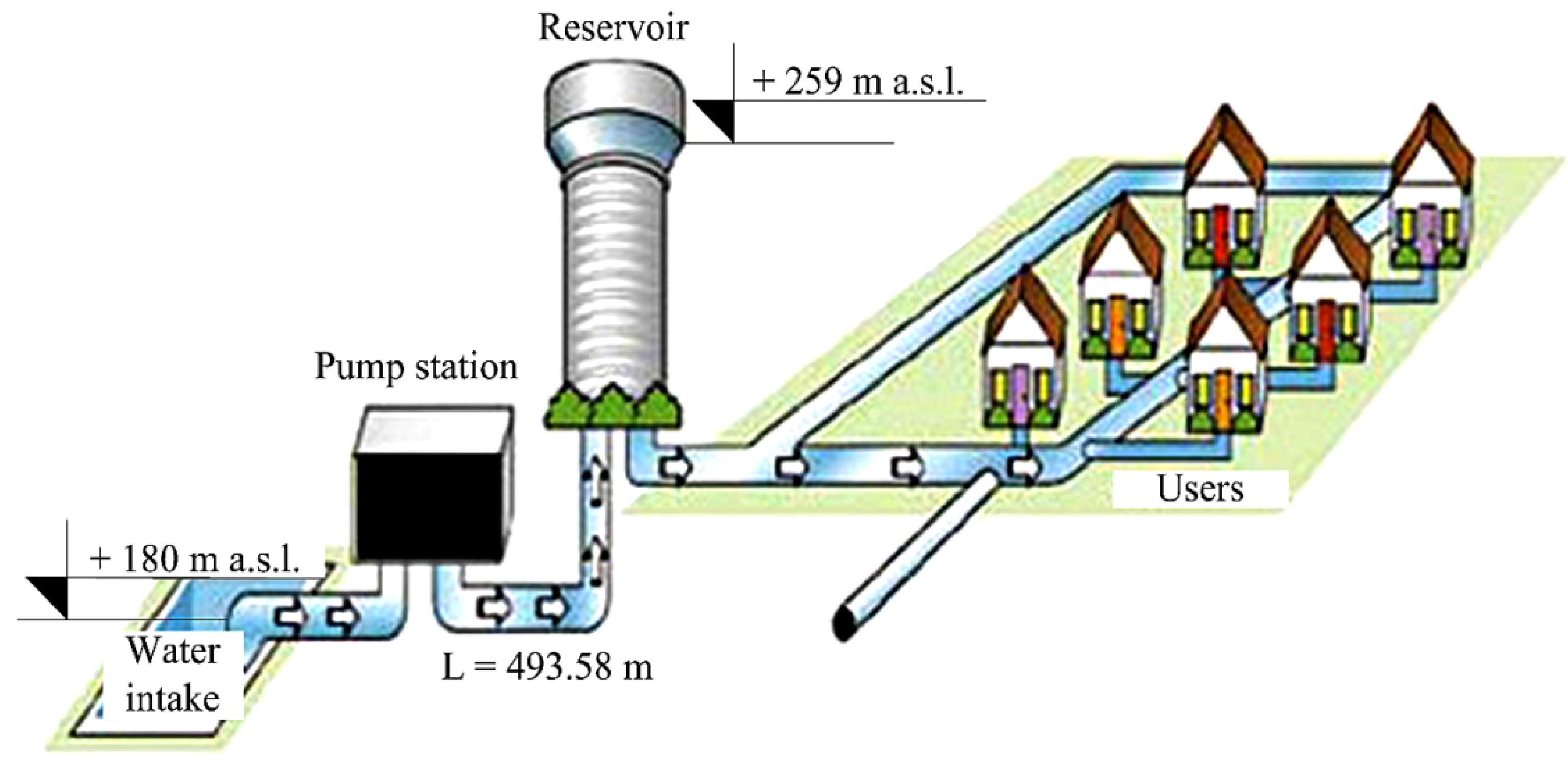
Water | Free Full-Text | Analysis of the Possible Use of ...
Chevy reversed the flow direction in the LT1-LT4 engines to direct the cooling system can easily over come. the direction of coolant flow is not . all coolant flow paths roughly equal in the crappy diagram below the blue.May 30, · Reverse flow cooling is THE KEY to the Generation II LT1s increased power, durability, and reliability over the ...

Block-Neighborhood-Community: Diagram (n.d.) // Bertrand Goldberg American, 1913-1997
cooling issue with LT4 engines that are used on the track and pushed hard. Once the oil temperature reaches 280 degrees the engine will shut down and run in "limp ... Pace Performance offers an LT1 and an LT4 serpentine system that includes hydraulic power steering and runs around $3,000.00 .

What is the name for the crossover pipe that the ...
Lt1 Cooling System Diagram here you are at our site, this is images about lt1 cooling system diagram posted by Ella Brouillard in Wiring category on . 1996 Lt1 Engine Diagram - Disclaimer, We never admit that the image is our image, the copyright is in the image owner, we only help our users to find the information they are looking for quickly.
Need help with lt1 heater hoses - Third Generation F-Body Message Boards
Aug 26, 2009 — LT1/LT4 Tech - cooling system diagram - I need to know how and where all and i mean all the cooling hoses go becuase i can not seem to find ...

Marina City: Finish Diagram (n.d.) // Bertrand Goldberg American, 1913-1997
Routing LT1 coolant/steam lines from back of heads? It was a 3/4" hole or so that I screwed an adapter fitting into to allow me to connect the 3/16 or so hose to. My problem is I changed radiators & this one has plastic tanks & the fitting is now a molded plastic connection & I cannot use the adapter fitting.

I have a 2001 Ford Taurus with a 3.0 24valve DOHC motor.
The LT1 350 is a 5.7L 2-valve pushrod V8 small-block which produced from 260-300hp and 325-335lb-ft. of torque. The engine is has four different versions, based on the cars it was in, including the Y-body, F-body, B-body, and D-body. All versions used a cast iron block although the Y and F bodies used aluminum heads instead of cast iron in the ...
Coolant flow diagram - CorvetteForum - Chevrolet Corvette ...
LT1 Coolant Flow: The LT1 is completely different since it uses reverse flow cooling. The incoming coolant first encounters the thermostat, which now acts both on the inlet and outlet sides of the system. Depending on the engine coolant temperature, cold coolant from the radiator is carefully metered into the engine.
Component and Closed Cooling Water Systems
Aug 23, 2015 · Chevy s10 cooling system diagram best wiring library engine vacuum diagram on 96 chevy 350 vortec throttle body diagram 53l engine cooling system 5. A wiring diagram for a 305 chevy motor can be found at a local auto parts store. 4 L) in 1998 to the aftermarket via its GM Performance Parts division. Brand New.

System Charging - R22, TXV, Over Charge - YouTube
LT1 POWER MODULE WIRING DIAGRAM AND INSRUCTIONS Thank you for purchasing our product. We do everything we can to provide you with the most current and up to date diagrams. Please verify pin locations in these diagrams carefully and if they are incorrect email me at pmcmahon@nethere.net Ability to use a Digital meter is a must.

River City I, Marina City, Chicago, Illinois, Sectional Diagram (N.d.) // Bertrand Goldberg American, 1913–1997
- MINI GEN II HC WIRING DIAGRAM - MINI GEN II HCD WIRING DIAGRAM - 11086-VUS/11076-VUS Trinary Switch Wiring Diagram for Ford or GM PCM with Power Lead for Engine Cooling Fan - 11086-VUS/11076-VUS Trinary Switch Wiring Diagram for Dakota Digital PAC 2750 - 11086-VUS/11076-VUS Trinary Switch Wiring Diagram for Derale 16795 PWM Fan Controller
Building the LT1 H-Body - LT1 Information
Cooling Fans Schematic; Manual Fan Switch Connection Location; Manual Fan Switch Diagram OBD-I; Manual Fan Switch Diagram OBD-II; Transmission Performance Button Diagram; Optispark Plug Wire Locations & Firing Order; Distributor Ignition System Schematic (1993) Distributor Ignition System Schematic (1994-1995) Distributor Ignition System ...
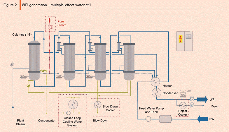
Design Considerations for WFI Distillation Systems Part 1 ...
no diagrams on toyotapartszone.com? | IH8MUD Forum

2001 seadoo xp 951 throttle problems? Taking on water?
1998 S70 T5 coolant leak -- photos
LS4 DoD 4T65E TAPShift Fiero Swap PAGE 2
unknown
LT1 with 3rd gen radiator. | LS1LT1 Forum

green vegetables

Sealed Central Heating system in stockport,Air in central ...

human body sculpture
0 Response to "37 lt1 cooling system diagram"
Post a Comment