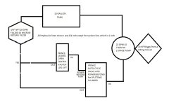
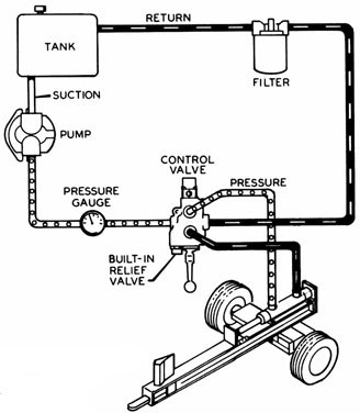
37 log splitter hydraulic diagram
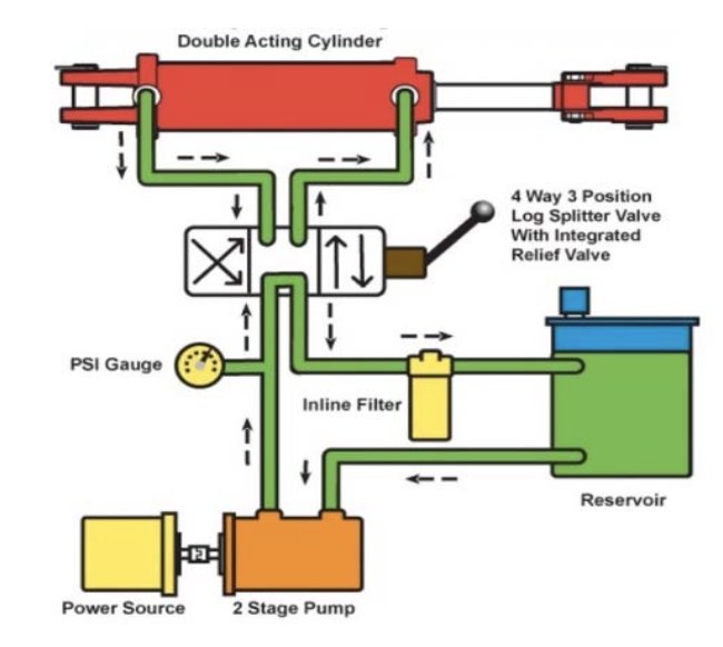
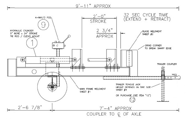
ONLY operate the log splitter from the operator zone as shown in the diagram. Operating the log splitter in another location can result in serious injury or death. • ALWAYS chock the wheels to prevent movement of the log splitter while in operation. • KNOW how to stop the log splitter and disengage the controls before operating it. This log splitter is a machine designed to split wood logs using a hydraulically powered moving ram that pushes the log against a splitting wedge. The log splitter's gasoline engine is used to pressurize the hydraulic system. This log splitter is designed to split logs up to 30" long and 24" in diameter, lengthwise with the grain only.
NEVER operate your log splitter near a flame or spark or smoke during operation. Hydraulic oil and gasoline are flammable and can explode. NEVER fill the gas tank while the engine is hot or running.Allow the engine to cool before refueling. ONLY refuel your log splitter in a clear area with no gas fumes or spilled gas.

Log splitter hydraulic diagram
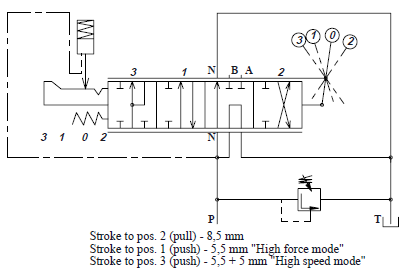
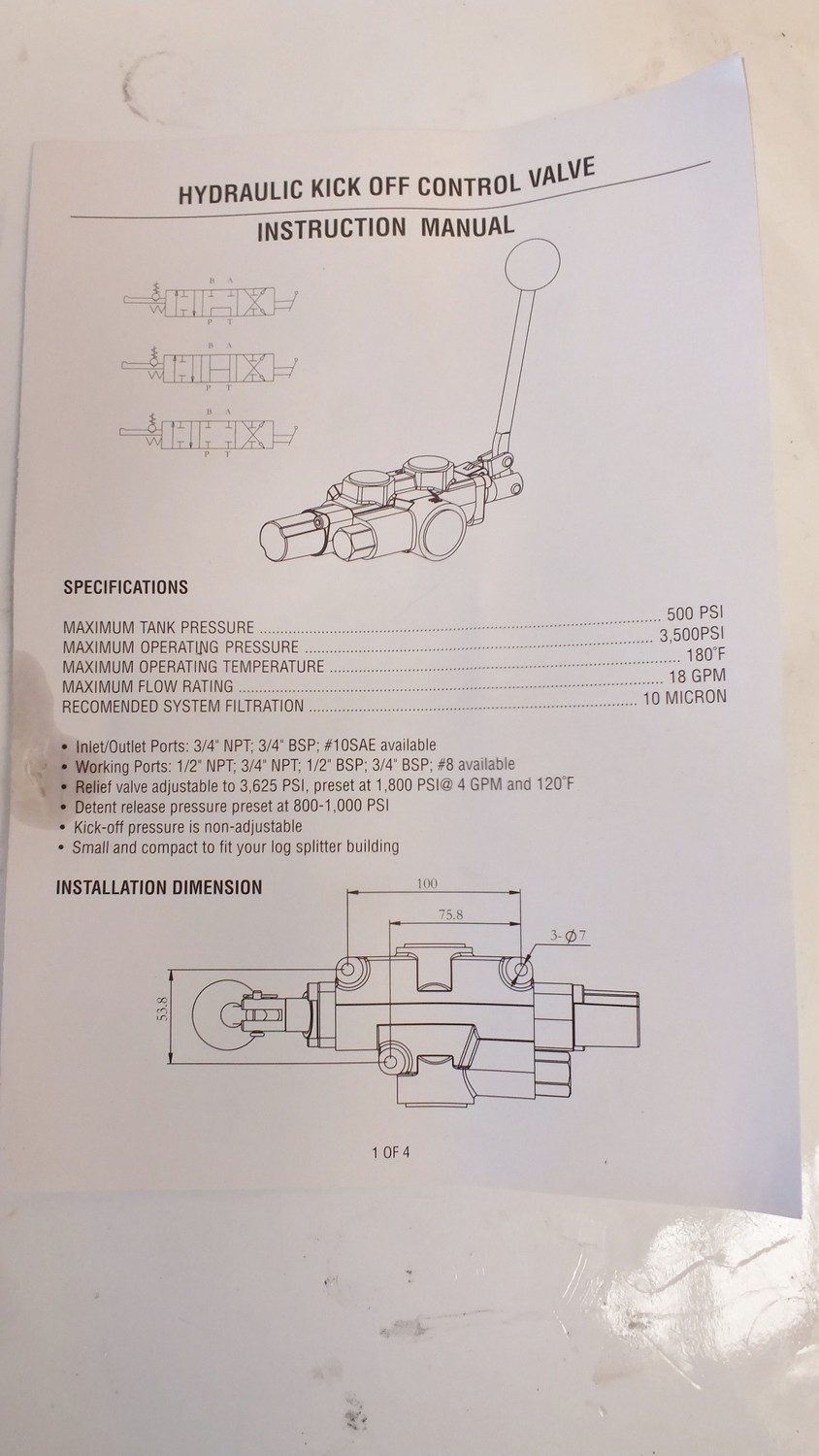
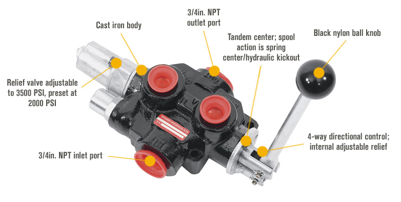
Power Equipment log splitter . CPE designs and builds log splitters to strict specifications . With proper use and maintenance, this log splitter will bring years of satisfying service . Portable Log Splitter This unit is a gasoline engine driven hydraulic log splitter . It is designed to split wood logs for use as fire wood for a stove or fire ... Gas Log Splitter Operator's Manual ... Assembly 12 Parts Diagram 25 ... Pay attention to all cautions and warnings. This unit is a gasoline engine driven hydraulic log splitter. It is designed to split wood logs for use as firewood for a stove or fireplace. This log splitter will only split logs lengthwise with the grain. LOGSPLITTER VALVES WITH HYDRAULIC KICK-OUT! The log splitter valve is a four-way hydraulic directional control valve designed to operate a two-way hy-draulic circuit from a single hydraulic source in an open center system. Pull handle out to extend cylinder. Handle is spring loaded, and will return to neutral when released.
Log splitter hydraulic diagram. Diagram showing the teeth of a saw blade when looking front-on. The teeth protrude to the left and right, so that the saw cut (kerf) is wider than the blade width. The term set describes how much the teeth protrude. The kerf may be sometimes be wider than the set, depending on wobble and other factors. Abrasive saw: A saw that cuts with an abrasive disc or band, rather than a … The hydraulic system of your log splitter requires careful inspection along with the mechanical parts. Be sure to replace frayed, kinked, cracked or otherwise damaged hydraulic hose and components. ... STEP 2: Attach the tongue (3) to the tank/axle (2) as shown in the diagram using the two 1/2 in. NC x 4-1/2 in. hex cap screws (75), 1/2 in. Log Splitter Replacement Parts. Don't see your part listed? We offer a complete line of replacement parts that are in stock and ready to ship, or find a store near you for service and repair. Call 1-800-657-0516 to Order. Mon - Fri 7:00 AM - 6:00 PM (CT) Sat 7:00 AM - 3:00 PM (CT) Log Splitter Parts: A well-maintained hydraulic system in your log splitter is necessary to ensure a smooth split on every log. If you have a leaky hydraulic hose or broken cylinder, the power of your log splitter can be lost. We carry replacement hydraulic cylinders, hoses, fittings, pumps, as well as new wedges and accessories for your log ...
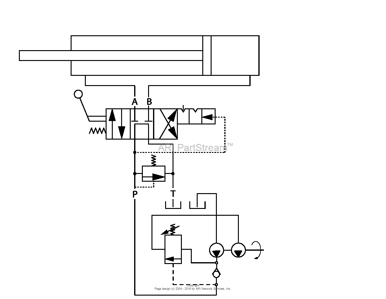
The hydraulic cylinder as it the backbone of any hydraulic log splitter. Its force the log into a metal wedge to split it into pieces (see splitting wedge heads). These hydraulic cylinders can be mixed and matched to the pump and power source but the hydraulic cylinder tonnage rating must not be below the hydraulic pump tonnage rating. Hydraulic Handpump. Up to 3500 psi working pressure "SA" Series is Single Acting "DA" Series have a built in Directional Control Valve; 1.5 and 2.1 Cubic Inch Per Cycle (One Up and One Down) Catalog Pages; Log Splitter. Pressure release detent at end of retract stroke ; Relief set at 2,250 psi ; Max tank port pressure 500 psi ; Max operating temperature 180° F; Catalog Pages; … The Log Splitter Hydraulic Circuit. Most log splitters use a hydraulic cylinder ( like these) to push a cut piece of log into a sharpened wedge, which splits it. The cylinder is driven by hydraulic oil, under pressure, produced by a hydraulic pump. An engine, or electric motor, drives the pump shaft, and supplies the power for the system. Electric Log Splitter Operator's Manual MODEL NUMBER YS0552 SERIAL NUMBER PURCHASE DATE ... Freeing a Jammed Log 9 Replacing Hydraulic Oil 10 ... Plumbing Diagram 11 Parts Diagram 12 Parts List 13 Carefully read through this entire operator's manual before using your new Log Splitter. Pay attention to all cautions and warnings.
1 Find the diagram. Find the diagram of the detent valve set up. There will be input valves for the pressurized and un-pressurized hose connections, and the diagram will show you which ones go on which side of the detent valve and in what order. If the hydraulic hoses are hooked up incorrectly, then the valve won't be able to function properly. 4 DR® 5-TON ELECTRIC LOG SPLITTER This is a high-powered machine, with moving parts operating with high energy. You must operate the machine safely. Unsafe operation can create a number of hazards for you, as well as anyone else in the nearby area. This log splitter is a machine designed to split wood logs using a hydraulically powered moving wedge. The log splitter's gasoline engine is used to pressurize the hydraulic system. This log splitter is designed to split logs lengthwise with the grain only. This log splitter model is capable of splitting logs up to 24" long and 16" in diameter. Power Equipment log splitter . CPE designs and builds log splitters to strict specifications . With proper use and maintenance, this log splitter will bring years of satisfying service . Portable Log Splitter This unit is a gasoline engine driven hydraulic log splitter . It is designed to split wood logs for use as firewood for a stove or ...
Description : Speeco S390406Sc Log Splitter Valve - Omni Mfg Llc with regard to Huskee Log Splitter Parts Diagram, image size 500 X 380 px, and to view image details please click the image. Here is a picture gallery about huskee log splitter parts diagram complete with the description of the image, please find the image you need.
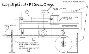
HOSE, HYDRAULIC SUCTION PUMP SUPPLY LOG SPLITTER 1 33 W1265V0808 FITTING, HYDRAULIC 34 W1265V0810 PIPE, NIPPLE 1/2 NPT VALVE SPACER ... Trail Warrior Quick Split 12-Ton Log Splitters W1265VCE, W1265BCE PaRTS DIaGRaM 1-866-373-9665 Order parts online at www.AltaPower.com or call 866-373-9665 M-F 8-5.

Northern Hydraulics stocks a variety of hydraulic log splitter replacement parts, accessories, and engines to get your unit running smoothly. Call 1-800-823-4937 for information on choosing the hydraulic log splitter pumps, valves or cylinders that are right for you.

Sep 27 2016 image result for log splitter hydraulic circuit diagram. A log splitter is a machine with several components that make short order work of splitting firewood quickly and with much less effort. A hydraulic circuit 21 30 38 42 44 46 46 48 having a predetermined maximum design pressure rating. If you have a wood burning fireplace or ...
Hydraulic issues in log splitters are typical like vibration or shaking, log splitter will not retract, etc. They are relatively easy to locate and troubleshoot. Hydraulic systems are based on the mechanism where a pressurized fluid is released, which acts as the driving force and powers the machine to split the log.

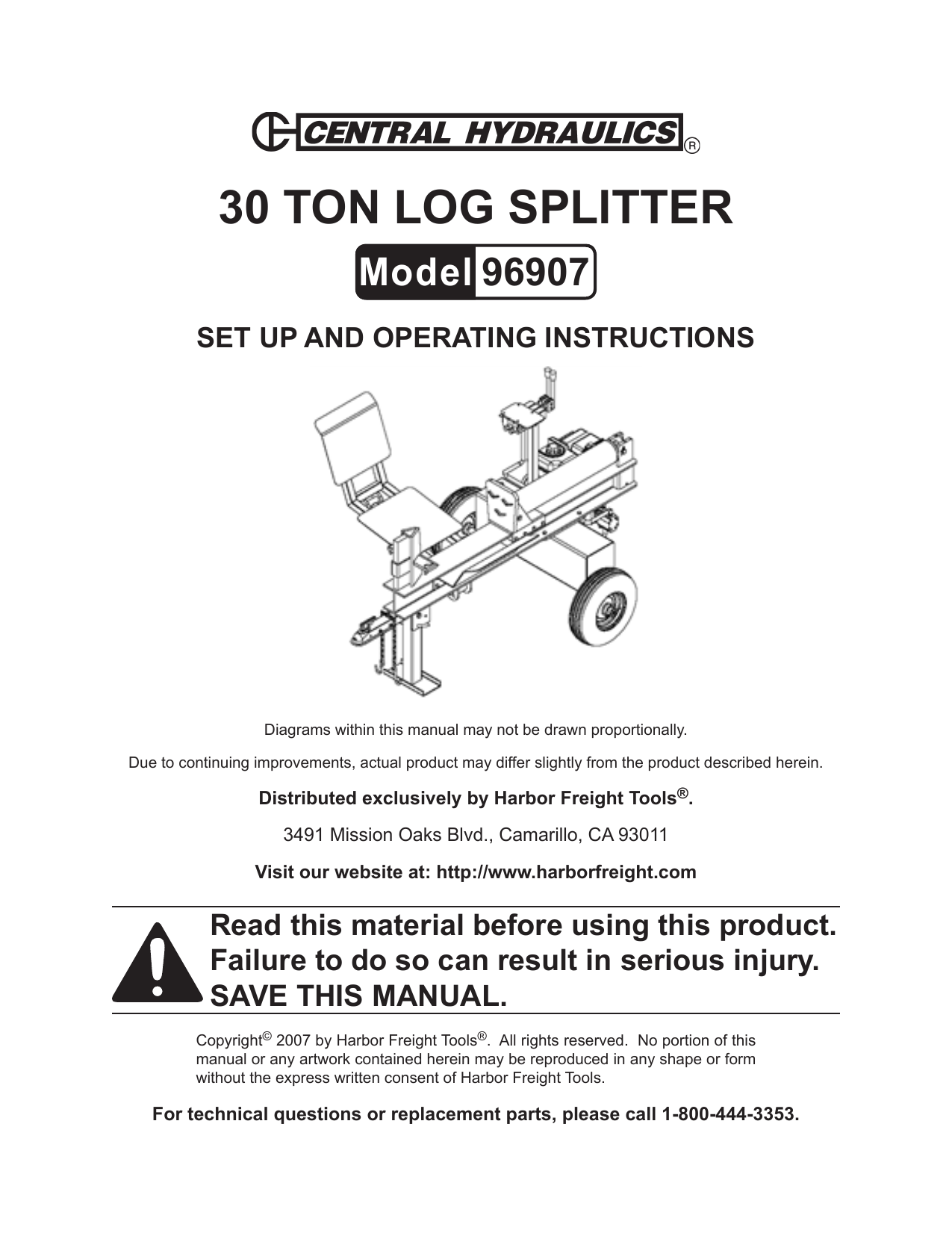
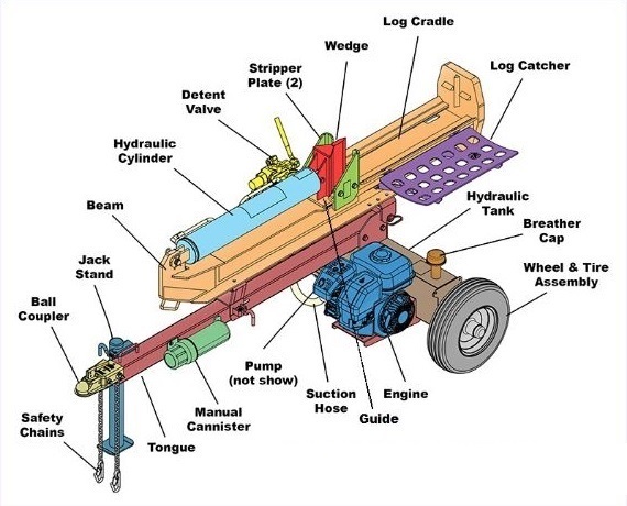
The hydraulic oil pump creates a stream of high-pressure oil, which runs to a valve. The valve lets the operator actuate the hydraulic cylinder to split a log. There is also a tank to hold the hydraulic oil that feeds the pump and usually a filter to keep the oil clean. Valves can apply both forward and backward pressure to the piston.
to ensure the log splitter works under pressure no more than is listed in the specifications. The setting was made by a qualified mechanic with professional instruments. Unauthorised resetting will reduce the performance of the hydraulic pump or RESULT IN SERIOUS INJURY AS WELL AS DAMAGE TO THE MACHINE. WIRING DIAGRAM HYDRAULIC DIAGRAM

The hydraulic system of your log splitter requires careful inspection along with the mechanical parts. Be sure to replace frayed, kinked, cracked or otherwise damaged hydraulic hose and components. ... STEP 2: Attach the tongue (3) to the tank/axle (2) as shown in the diagram using the two 1/2 in. NC x 4-1/2 in. hex cap screws (75), 1/ 2 in.

Hydraulic Oil Reservoir Log Splitter Valve Auto Cycle Valve . Open Center hydraulic Valve: There are two basic valve systems used on log splitters: They come with different options . 1-Log splitter valve - You have to hold the valve lever on the splitting stroke & on the return stroke, there is a detent to
Log Splitter Hydraulic Troubleshooting 9 - 17 2. With the log splitter off, cycle the control valve forward and rearward several times to relieve any pressure in the hydraulic system._____ See Figure 2. 3. Remove the high pressure hydraulic hose from the inlet port of the control valve using channel locks and a (1 and 1/8") wrench._____
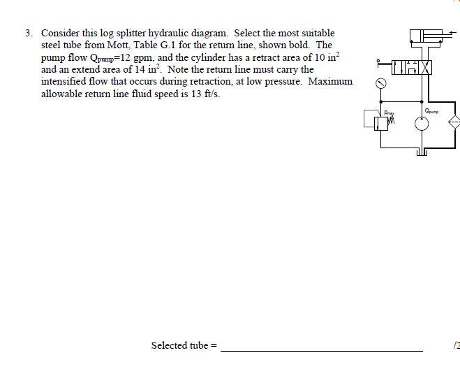
Most commercially available log splitters use a hi-lo pump, which is essentially two pumps in one — a high-pressure, low-flow pump and a low-pressure, high-flow pump operating in tandem. In normal operation, both pumps route fluid to the cap end of a cylinder. When a wedge mounted to the cylinder's rod end engages the log, system pressure ...
I need a hydraulics diagram for building my own wood splitter, it will have two cylinders, one for splitting and one for a lifting tray to lift bigger pieces onto the splitter. the hydraulic pump I got has three ports one large port that comes from the oil reservoir [ this I know ] and the two other smaller ports are located on either side of the larger port. are these smaller ports pressure ...

Fig. 2 is a side schematic diagram of the log splitter shown in Fig. 1 Fig. 3 is a cross sectional side elevational view of the hydraulic control valve, cylinder and ram of the present invention. Fig. 4 is an enlarged fragmentary cross sectional View of the control valve of Fig. 3 in which the valve is in a neutral position.

LOGSPLITTER VALVES WITH HYDRAULIC KICK-OUT! The log splitter valve is a four-way hydraulic directional control valve designed to operate a two-way hy-draulic circuit from a single hydraulic source in an open center system. Pull handle out to extend cylinder. Handle is spring loaded, and will return to neutral when released.
Gas Log Splitter Operator's Manual ... Assembly 12 Parts Diagram 25 ... Pay attention to all cautions and warnings. This unit is a gasoline engine driven hydraulic log splitter. It is designed to split wood logs for use as firewood for a stove or fireplace. This log splitter will only split logs lengthwise with the grain.
Power Equipment log splitter . CPE designs and builds log splitters to strict specifications . With proper use and maintenance, this log splitter will bring years of satisfying service . Portable Log Splitter This unit is a gasoline engine driven hydraulic log splitter . It is designed to split wood logs for use as fire wood for a stove or fire ...


0 Response to "37 log splitter hydraulic diagram"
Post a Comment