36 block diagram reduction rules
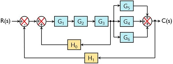
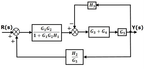
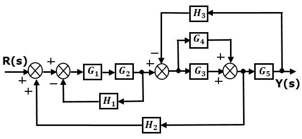
Block Diagram Reduction Rules Follow these rules for simplifying (reducing) the block diagram, which is having many blocks, summing points and take-off points. Rule 1 − Check for the blocks connected in series and simplify. Rule 2 − Check for the blocks connected in parallel and simplify.
Control Systems: Block Diagrams Reduction RulesTopics Discussed:1. Shifting of Take-off Point before an Adder.2. Shifting of Take-off Point after an Adder.3....
Block Diagram Reduction Rules - Control System. We have discussed in our previous article that for the easiness of analysis of a control system, we use block diagram representation of the control system. Basically we know that a complex system is difficult to analyze as various factors are associated with it.

Block diagram reduction rules
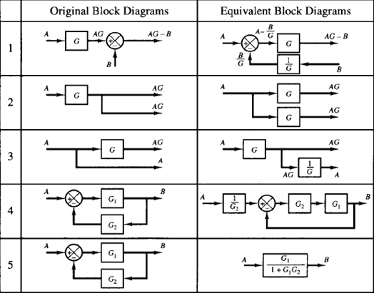
Block Diagram Reduction Rules Block diagram reduction rules help you to minimize the block diagram thus solving the equations quickly. Below table represents block diagram reduction rules in the control system Using the above rules you have to follow below simple steps to solve the block diagrams: 1. Combine all cascade blocks 2.
Rules for Block Diagram Reduction. Any complex block diagram representing a system can be reduced to a simple block diagram for determining the transfer function by applying certain rules. The rules that can be used in simplifying the given complex block diagram are as explained below. Proof for the rules is obtained by determining the output ...
(s), using block-diagram reduction rules. Task 2: Develop a Simulink model for the original system in Figure 8. Set the reference signal input, r v (t)=4 u(t), as a step input with a zero initial value, a step time= 0 seconds, and a final value of 4 volts. Use X-Y graphs to display (over the period from 0 to 8 seconds)
Block diagram reduction rules.
Block Diagram Reduction Rules Following rules are used for simplifying (reducing) the block diagram, which includes many blocks, summing points and take-off points. Rule 1 − Check for the blocks connected in series and simplify.
Block Diagram Reduction Rules Follow these rules for simplifying (reducing) the block diagram, which is having many blocks, summing points and take-off points. Rule 1 − Check for the blocks connected in series and simplify. Rule 2 − Check for the blocks connected in parallel and simplify.
Learn all the block diagram reduction rules just by watching this one simple video.Two Critical Laws Explanation (Please watch video along with this descript...
Block Diagram Reduction W.3 4Mason™s Rule and the Signal-Flow Graph A compact alternative notation to the block diagram is given by the signal-⁄ow graph introduced Signal-⁄ow by S. J. Mason (1953, 1956). As with the block diagram, the signal-⁄ow graph o⁄ers a visual tool for graph
K. Webb MAE 4421 3 Block Diagrams In the introductory section we saw examples of block diagrams to represent systems, e.g.: Block diagrams consist of Blocks-these represent subsystems - typically modeled by, and labeled with, a transfer function Signals- inputs and outputs of blocks -signal direction indicated by
A block diagram is a representation of a system using blocks. For representing any system using block diagram, it is necessary to find the transfer function ...
Block Diagram Reduction techniques 2G1G 21GG 2. Moving a summing point behind a block G G G 1G 2G 21 GG + 1. Combining blocks which are in cascade or in parallel. 5. 5. Moving a pickoff point ahead of a block G G G G G 1 G 3. Moving a summing point ahead of a block G G G 1 4. Moving a pickoff point behind a block.
Block Diagram • It represents the structure of a control system. • It helps to organize the variables and equations representing the control system. It is composed of: • boxes, that represents the components of the system including their causality; • Lines with arrows, that represent the actual
Block Diagram Reduction Figure 1: Single block diagram representation Figure 2: Components of Linear Time Invariant Systems (LTIS)
Rules for Block Diagram Reduction - Digital Electronics Download Now Download. Download to read offline. Education. Aug. 12, 2017 3,862 views This document contains the detailed note on how to reduce the block diagram with some defined steps.It also contains an example for the better conceptualization of this topic.
160 BLOCK DIAGRAM ALGEBRA AND TRANSFER FUNCTIONS OF SYSTEMS [CHAP. 7 Let the - 1 block be absorbed into the summing point: Step 4c Step 5: By Equation (7.3), the output C, due to input U is C, = [G2/(1 + G1G2)]U. The total output is C=C,+C,= [ ~ 1 +G2G2] [ A] [ A] IGIR + 7.8 REDUCTION OF COMPLICATED BLOCK DIAGRAMS The block diagram of a practical feedback control system is often quite complicated.
2.1 Rules for Block Diagram Reduction: Now the following block diagram algebra is often used to describe rules for reduction: Rule 1: Blocks in cascade Two or more blocks in cascade may be combined in one block. Rule 2: Combining Blocks in Parallel Two blocks or more in parallel may be combined in one block as the algebraic sum. X(G 1 (s) G X(s ...
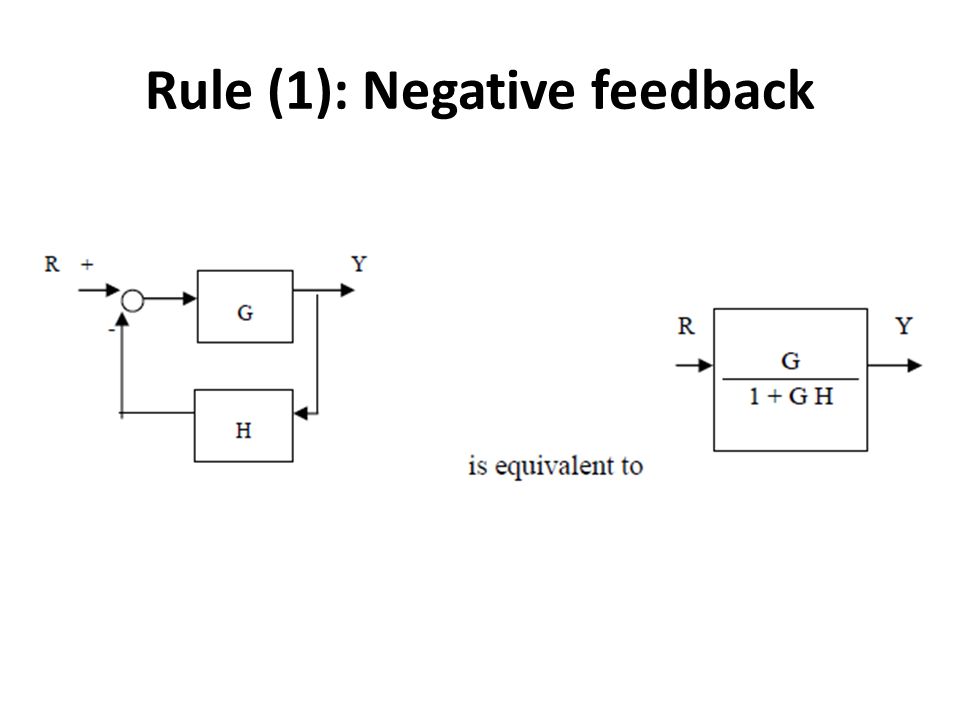
Rule: 6 (Negative Feedback loop). Negative Feedback. Simplify models of systems with interconnected components using block- diagram reduction; Manipulate linear models as transfer-function or state-space data. Consider the block diagram shown in the following figure.
Lets simplify it step-by-step using block diagram reduction rules. Step-1 :- Use rule 4 for shifting take-off point after block G3 . Step-2 :- Use rule 1 for blocks G2 and G3 . Step-3 :- Use rule 6 for loop containing blocks G2G3 and H2 . Step-4 :- Use rule 1 for blocks G1 and G2G3/ (1+ G2G3H2) . Step-5 :- Finally, use rule 6 to get simplified ...
Control Systems: Block Diagrams Reduction RulesTopics discussed:1. Representation of a closed-loop system.2. Reduction rule when the blocks are connected in ...
Block Diagram Reduction Rules.pdf -. School Taylor's University. Course Title CHEM 62004. Uploaded By Aftab232323. Pages 2. This preview shows page 1 - 2 out of 2 pages. View full document. End of preview.
Block diagram reduction rules Rule No.1. Blocks in Cascade When two or more blocks are connected in series, then the resultant block is the product of the individual blocks. Rule No.2 Blocks in parallel When two or more blocks are connected in parallel, then the resultant block is the sum of the individual blocks.
Block diagram reduction rules Rule No.1. Blocks in Cascade When two or more blocks are connected in series, then the resultant block is the product of the individual blocks. Rule No.2 Blocks in parallel When two or more blocks are connected in parallel, then the resultant block is the sum of the individual blocks.
block diagram reduction solved problems. 1. Block Diagram Reduction Problems - Ameya P. Nijasure napradeep@mes.ac.in Do visit Block Diagram Reduction rules (.ppt) 2. Problem 01 Simplify the following block Diagram & determine closed loop transfer function. 3. Problem 01 STEP 01STEP 01 Rule 02: Blocks in Parallel. 4.
Fig. 7. (a) Block diagram of a dynamic system; (b1)-(g1) successive reductions of the block diagram by relocating summing point A; (b2)-(g2) successive reductions by relocating pickoff point B. Table 2. Rules to be applied for simplifying the block diagram shown in Fig. 7(a) The current approach The proposed alternative approach Rules to be ...
Block diagram reduction rules: Rule 1: Moving the branch point ahead of the block: Rule 2: Moving the branch point before the block: Rule 3: Moving the summing point ahead of the block. Rule 4: Moving the summing point before the block. Rule 5: Interchanging the summing points. Application:
Table 1: Block Diagram Reduction Rules Table 2: Basic rules with block diagram transformation . Example 1: Example 2: Example 3: Example 4: Example5: ECE 680 Modern Automatic Control Routh's Stability Criterion June 13, 2007 1 ROUTH'S STABILITY CRITERION Consider a closed-loop transfer function H(s) = b 0sm +b
Block diagram reduction technique . Because of their simplicity and versatility, block diagrams are often used by control engineers to describe all types of systems. A block diagram can be used simply to represent the composition and interconnection of a system.
The technique of combining these blocks is referred to as the block diagram reduction technique. For the successful implementation of this technique, some rules for block diagram reduction to be followed. Let us discuss these rules, one by one, for the reduction of the control system block diagram.












0 Response to "36 block diagram reduction rules"
Post a Comment