35 copeland potential relay wiring diagram
06.03.2021 · If the thermostat wiring will be located near or in parallel with high voltage wiring, cable TV or Ethernet wiring, then shielded thermostat wire can be used to reduce or eliminate potential interference. The shield wire should be connected …
18.08.2021 · More than a year-and-a-half into the COVID-19 pandemic, burnout seems to be on everyone’s lips. Many of us didn’t realise what had hit us when we scrambled to adjust to the sudden upheaval of the workplace, switching to remote work with little or no preparation, or deemed an essential worker and asked to continue business-as-usual in highly unusual …
Jun 25, 2020 · Potential relay wiring diagram compressor potential relay wiring diagram copeland potential relay wiring diagram mars potential relay wiring diagram every electrical arrangement consists of various distinct components. Relays/Switches/Diode Wiring Diagrams. Assortment of 12v relay wiring diagram spotlights.

Copeland potential relay wiring diagram
Trane capacitor replacement. Trane capacitor replacement
• Low Voltage- Voltage at compressor terminals is lower than specification, check compressor contactor, system wiring, system disconnect. • Incorrect motor wiring – Verify compressor and system wiring. • Loose electrical connections – Verify all electrical connections are tight and do not show signs of heat or arcing.
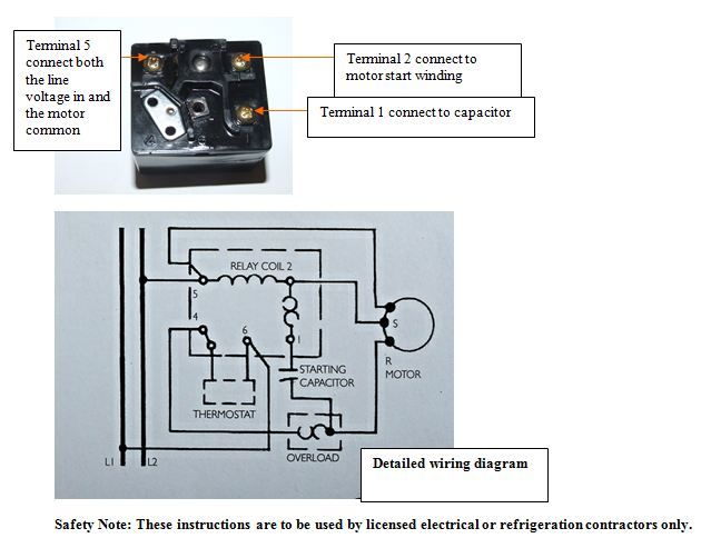
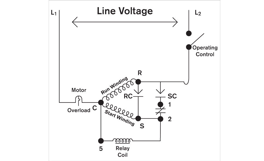
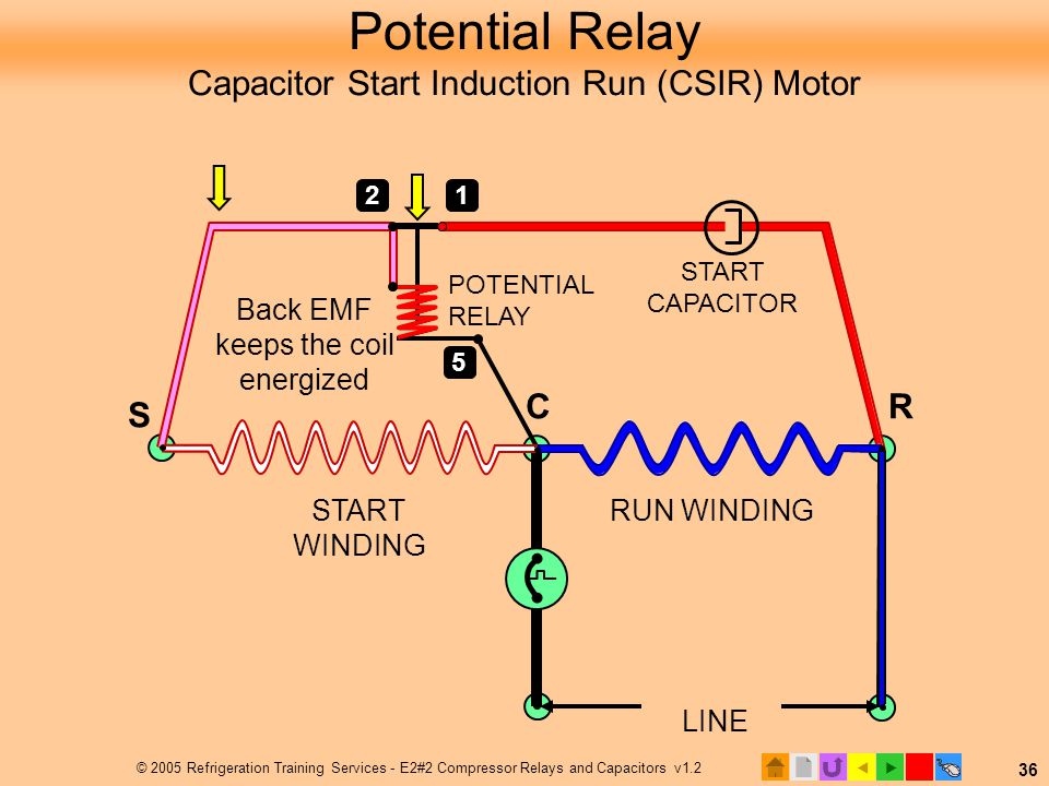
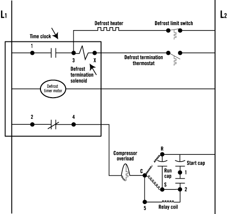
Copeland Potential Relay Wiring Diagram Nov 12, of the relay to disconnect the start capacitor at a speed where the motor has Circuits. If there is a terminal in position #6, it must be the same polarity as terminals #1, MOTOR START POTENTIAL RELAY. 50 Amperes max.
Copeland potential relay wiring diagram.
Products, Software & Services: The Most Complete Portfolio in the Industry Emerson helps manufacturers achieve top quartile business performance through the industry’s broadest portfolio of technologies to measure, control, optimize and power their operations – and the experience and expertise to solve their toughest problems.
Electric motor start-run capacitor instructions: Use of air conditioner compressor motor starting capacitors Use of starting capacitors on electric motors for air conditioning, pumps, etc. Capacitors are electric devices that get an electric motor running at start-up or that help keep a motor running once it has started. If the capacitor has failed the symptom is that the motor …
12.07.2017 · 727 neutral safety switch wiring diagram; 8 pin relay wiring diagram; 8 pin relay wiring diagram pdf; 8 pin rocker switch wiring diagram; 87 supra fuse box diagram; 900 schematic signal stat 900 wiring diagram; 97 honda accord stereo wiring diagram; 97 subaru impreza fuse box diagram; 98 dodge ram trailer wiring diagram; 98 ford expedition ...
Wholesaler Copeland® GE P/N Pick-up Drop Out Cont. Volt Freq. P/N Brand P/N Volts Volts Rating Potential Relay Data 940-0001-82 040-0166-39 3ARR3T3U5 220 - 240 40 - 90 332 60
Copeland Potential Relay 040 0166 19 Wiring | Wiring Diagram – Potential Relay Wiring Diagram You are able to often depend on Wiring Diagram as an important reference that may assist you to preserve money and time. With the assist of this e-book, you’ll be able to very easily do your own personal wiring tasks.
An admission essay is an essay or other written statement by a candidate, often a potential student enrolling in a college, university, or graduate school. You can be rest assurred that through our service we will write the best admission essay for you. Reviews. Editing Support.
Potential Relays. Motors For Copeland Semi Hermetic Compressors. Single Phase Wire Diagrams. Electrical Handbook. Final2 Online Version A4 Cdu Catalogue 20pp. Know your potential starting relays solid state p m relay model pm a3c2 what happened to copeland electrical handbook ac compressor csr wiring diagram pdf basic controls of air symptom ...
A – Hermetic Compressors Emerson Climate Technologies 2014DS-78 R2 (2/16)4 AF - Compressor Parts Model Start Capacitor Run Capacitor Current Relay Potential Relay Overload
4 copeland semi hermetic compressor product catalogue feb 2010 by andrew tan lee issuu motors for compressors emerson electronics stream installation guide manuals technical information china scroll wiring diagram zr125kc e tf5 522 manual zr bush of coowor com como vestir a los 50 años hombres get 42 ac csr manualzz 4mf 13x application manuallines pdf manualslib electrical… Read More »
Copeland Potential Relay Wiring Diagram. Know your potential starting relays achr news 10 3 4 solid state and devices 5 motor bearings 6 drives components for electric motors what happened to terminal hvac p m relay model pm a3c2 air conditioning spare parts suppliers wholers in dubai electrical handbook good evil the hard start school basic ...
Copeland Potential Relay Wiring Diagram. Print the electrical wiring diagram off plus use highlighters in order to trace the routine. When you make use of your finger or perhaps stick to the circuit together with your eyes, it is easy to mistrace the circuit. 1 trick that I use is to print exactly the same wiring picture off twice.
Copeland Compressor Wiring Diagram. accordance with the position of the capacitors and relay shown on the wiring diagram. Compressor model. Run capacitor. Start capacitor. Potential relay. MISWIRING IS MURDER. It is very easy to miswire a compressor, but the results can be deadly. The purpose of this booklet is to dem- onstrate how to wire a.
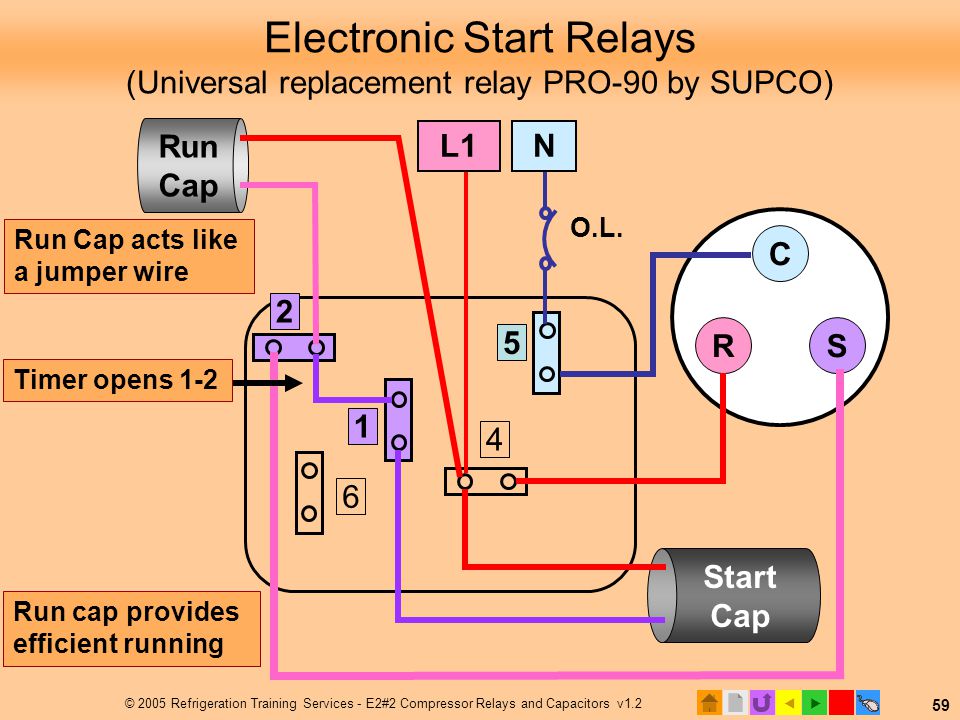
A more convenient method for providing increased torque to the compressor is the 2-wire potential relay hard start device. In this case, the device can add as much starting torque as a 3-wire hard start, but installation is made simpler and cost is usually lower. The Figure [shown here] illustrates the wiring diagram for a 2-wire hard start.
Potential Relay Wiring Diagram – compressor potential relay wiring diagram, copeland potential relay wiring diagram, mars potential relay wiring diagram, Every electrical arrangement consists of various distinct components. Each part should be set and connected with different parts in particular way. If not, the structure won’t function as it should be.


![Copeland Electrical Handbook - [PDF Document]](https://reader021.docslide.net/reader021/html5/20170803/55cf9b5c550346d033a5c516/bg4.png)


![WRG 8228] Potential Relay Wiring Diagram | Hvac air ...](https://i.pinimg.com/564x/73/ab/e6/73abe674629c0c5126dd4aca577bad05.jpg)



0 Response to "35 copeland potential relay wiring diagram"
Post a Comment