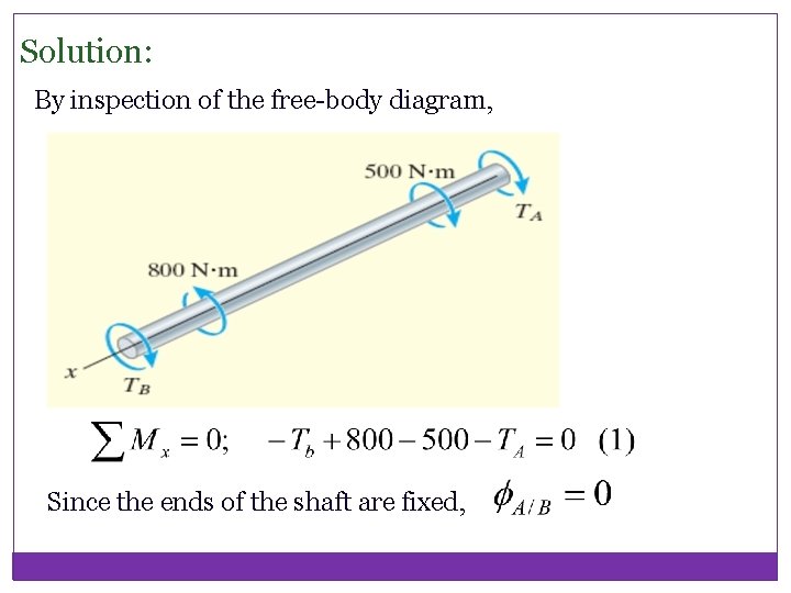
40 torque diagram for shaft
468. 1. Homework Statement: Draw a FBD, determine the largest torque, T1, and find shear stresses in CD and DE. Relevant Equations: Method of sections, static equilibrium. shear stress=Tc/J. I wish to draw a proper free-body diagram for this shaft. However, my FBD does not agree with the solutions manual. **Download Link** **https://www.aservicemanualpdf.com/downloads/1986-1994-jaguar-xj6-service-repair-manual** **This is the Highly Detailed factory service repair manual for the1988 JAGUAR XJ6, this Service Manual has detailed illustrations as well as step by step instructions,It is 100 percents complete and intact. they are specifically written for the do-it-yourself-er as well as the experienced mechanic.1988 JAGUAR XJ6 Service Repair Workshop Manual provides step-by-step instructions ba...
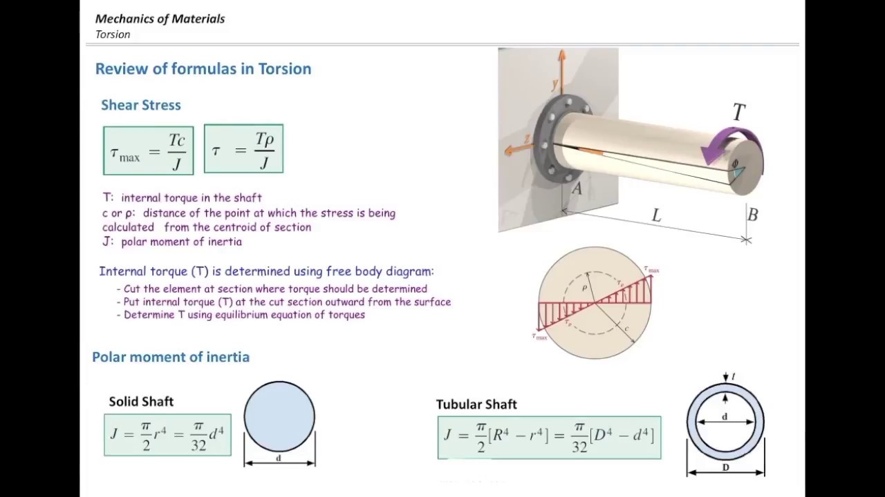
Torque Diagram and Torsional Stress of Circular Section Torsional or twisting moment is caused by forces whose resultant does not pass through the axis of rotation (called the shear center) of the structural member. Typically, significant torsions are induced in shafts of

Torque diagram for shaft
T na Tne Torque In the shaft between the gears, 2400 (0.3/2Y 360 N.m Generate shear-moment diagrams for two planes. 360 28 2 422 — 1439 8822 3331 X N N Solution Perform free body diagram analysis to get reaction forces at the bearings. By = 422 N The "Torque Sequence" column shows which diagram to use as the specific bolt torquing sequence for your engine . All diagrams can be found in numerical sequence at the back of this publication . Readers (if indeed there are any left) may recall that I have a 1979 Honda 400 engine in parts. I’ve done the work I originally dismantled it for and am now reassembling it - very slowly and cautiously. It’s a parallel twin and has a chain driven balancer mechanism to smooth out the engine. I’ve had all sorts of fun trying to get the balancer setup correct. Last time I did it the crank was really hard to turn and as I had forgotten to replace a seal anyway, I took it apart to redo. My first act...
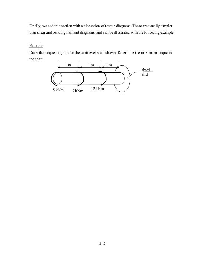
Torque diagram for shaft. I sexually identify as an attack helicopter. I lied. According to US Army Technical Manual 0, The Soldier as a System, “attack helicopter” is a gender identity, not a biological sex. My dog tags and Form 3349 say my body is an XX-karyotope somatic female. But, really, I didn’t lie. My body is a component in my mission, subordinate to what I truly am. If I say I am an attack helicopter, then my body, my sex, is too. I’ll prove it to you. When I joined the Army I consented to tactical-role gend... Draw a free-body diagram of the shaft on either side of the cut Use a static-equilibrium equation and the following sign convention to obtain the internal torque at the section Sign Convention Using the right-hand rule, the torque and angle of twist will be positive, provided the thumb is directed outward from the shaft when the problem is to calculate the internal torque in the shaft given the external loadings. Once we have plotted the torsion diagram, it is then easy to read off the maximum internal torque experienced by the shaft. 1) Equilibrium for equating forces and moments on free body diagrams, Part II: Stresses Induced by Torsion Hide Text When a shaft is subjected to a torque or twisting a shearing stress is produced in the shaft. The shear stress varies from zero in the axis to a maximum at the outside surface of the shaft. The shear stress in a solid circular shaft in a given position can be expressed as: τ = T r / J (1) where. τ = shear stress (Pa, lbf/ft2 (psf))
The sprocket that connects to the motor. Honda 2017 crf125f parts diagram shows no snap ring, some options on Amazon offer it, Are those short bolts universal? Even Home Depot or my local dirt bike shop could have them??? I think it’s a 428 pitch chain system. Need help. I guess it’s called the primary drive sprocket. It has two bolt holes and a “purpose built”. Washer I guess I would call it. That goes on top. What keeps that sprocket and washer from backing out or off the sh... The torque diagram of a shaft is analogues to the shear force and bending moment diagram of a beam. It is an important engineering diagram from the pulley shaft design point of view. The steps required to draw it will be discussed with the help of the following example: on the shaft will be held in position axially and how power transmission from each element to the shaft is to take place. Intermediate Shaft Mott, 2003, Machine Elements in Mechanical Design Procedure con't 6. Determine the magnitude of torque that the shaft sees at all points. • It is recommended that a torque diagram be prepared. 7. Teams of workman pull on great ropes as a great pole is lifted into a skeletal airship, coming to rest on a row of curved supports. On one end is a small cylinder of dense, mottled, green and gold wood, seeming almost as if it had been varnished purely through the extend of its natural oils. At the other is a rather innocuous hub to which four great blades of wood and cloth will be attached, nearly identical to those on large windmills. Interrupting its otherwise nearly constant profile are two ...
**Download Link** **https://www.aservicemanualpdf.com/downloads/1986-1994-jaguar-xj6-service-repair-manual** **This is the Highly Detailed factory service repair manual for the1992 JAGUAR XJ6, this Service Manual has detailed illustrations as well as step by step instructions,It is 100 percents complete and intact. they are specifically written for the do-it-yourself-er as well as the experienced mechanic.1992 JAGUAR XJ6 Service Repair Workshop Manual provides step-by-step instructions ba... TORQUE ON THE SHAFT: Data given earlier: P = 65 HP n= 2750 rpm Overall torque on the shaft = Torque at Gear 2 = Torque at Gear 3 = Torque at Gear 4 = .˘ ˇ ˆ ˙˝˛˚˜ The torque diagram show the torque applied at all parts of the shaft line . At points 7, 8 and 9 the max torque of 1489 lb ! ˇ ˝˛˚˜. ˜ "#$ 7:38In this video, we cover an introductory mechanics of materials concept, how to draw an internal torque diagram!25 Aug 2016 · Uploaded by AF Math & Engineering Draw the torque diagram for each shaft. PROBLEM 5-3 The solid shaft is fixed to the support at C and subjected to the torsional loadings shown. Determine the shear stress at points A and B and sketch the shear stress on the volume elements located at these points.
Space Diagram Torque Loads And Bending Moment Acting On The Blower Shaft Download Scientific Diagram
The torque diagram will plot out the internal torsional moment within a shaft that is supporting multiple inputs and/or outputs along its length. The most relevant practical scenarios that match this description are shafts within complex gear or pulley driven systems. This line shaft has a single input delivering torques to multiple outputs via ...
Theory C3 3 Angle Of Twist Solid Mechanics I
**Download Link** **https://www.aservicemanualpdf.com/downloads/1986-1994-jaguar-xj6-service-repair-manual** **This is the Highly Detailed factory service repair manual for the1994 JAGUAR XJ6, this Service Manual has detailed illustrations as well as step by step instructions,It is 100 percents complete and intact. they are specifically written for the do-it-yourself-er as well as the experienced mechanic.1994 JAGUAR XJ6 Service Repair Workshop Manual provides step-by-step instructions ba...
1
In this video, we solve a torque diagram without having to use equations. By simply looking at the external loadings, we can easily draw the internal torque...

Example 5 Etu Edu 5 1 The Stress Distribution In A Solid Shaft Has Been Plotted Along
Honda 2017 crf125f parts diagram shows no snap ring, some options on Amazon offer it, Are those short bolts universal? Even Home Depot or my local dirt bike shop could have them??? I think it’s a 428 pitch chain system. Need help. I guess it’s called the primary drive sprocket. It has two bolt holes and a “purpose built”. Washer I guess I would call it. That goes on top. What keeps that sprocket and washer from backing out or off the shaft?? And also, had a mechanic friend c...

Analysis Of Shaft Torque Amplification Caused By Interaction Between Ac And Dc System Semantic Scholar
The dynamometer lab test should be preformed at an input shaft torque level of 165 N·m and an input shaft speed of 3000 rpm. Because the PG torque and revolution information is measure from the propshaft, the transmission output, the data must be converted to determine the PG transmission input torque and revolutions.
Solved Draw The Moment Torque Diagram For The Shafts Shown Chegg Com
Draw the torque diagram fot the shaft shown below. If the tubular shaft is made from material having an allowable shear stress of {eq}\tau_{allow} {/eq} = 85 MPa, determine the minimum wall ...
Web Ncyu Edu Tw
I sexually identify as an attack helicopter. I lied. According to US Army Technical Manual 0, The Soldier as a System, “attack helicopter” is a gender identity, not a biological sex. My dog tags and Form 3349 say my body is an XX-karyotope somatic female. But, really, I didn’t lie. My body is a component in my mission, subordinate to what I truly am. If I say I am an attack helicopter, then my body, my sex, is too. I’ll prove it to you. When I joined the Army I consented to tactical-role gend...
Maximum Shear Stress And Angle Of Twist Mechanical Engineering
The conventional wisdom on torque consists of two major tenets: 1) Players who tend to hook the ball will benefit from a lower torque shaft. Players who tend to slice the ball will benefit from a higher torque shaft. 2) Players who swing faster need lower torque. This assumption is built right into most shafts by the manufacturers: take ...
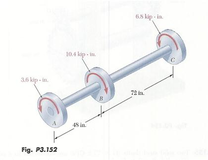
Solved Torques On A Steel Shaft Concentrated Torques On A Chegg Com
Hi everyone, I'm currently embarking on a project to design a PID control system for a DC motor, I've looked up on the internet and see many model that basically follow a work flow like [this](https://www.researchgate.net/profile/Robert-Babuska/publication/267784685/figure/fig2/AS:669493776891908@1536631163751/SIMULINK-block-diagram-of-the-DC-motor-with-a-PID-controller.png). However, after solving the ODE equations, I've found out that the angular velocity of the motor's shaft is directly p...
Create Torque Diagram For Pulley Shaft Design
shaft is proportional to the applied torque and to the shaft length. L T ∝ ∝ φ φ Shaft Deformations • When subjected to torsion, every cross -section of a circular shaft remains plane and undistorted. • Cross-sections of noncircular (non-axisymmetric) shafts are distorted when subjected to torsion. • Cross-sections for hollow and ...

Mechanical Torsion Meter Principle Inst Tools
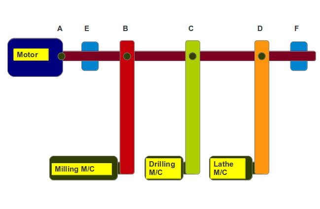
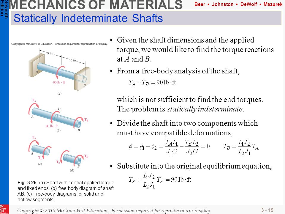
torque diagram for the shaft. Apply the force method. Concepts involved: Statically indeterminate structures Force method of analysis In this method the problems are reduced to statical determinancy by removing one of the redundant reactions and calculating the rotation θo at the released support. The required

Torque Measuring Shafts Sensors Transducer
[gen.](https://i.ytimg.com/vi/0ZU5AMlx_38/hqdefault.jpg) (note the gearbox is bigger than the generator, compare size of input shaft to output; this high-torque factor is why generators are mounted in the difficult-access position, high above ground; see Torque Management section below). [part 1](https://www.reddit.com/r/AlternativeHypothesis/comments/mzmwvx/windturbine_design_alternatives/?) Null Hyp. [Horizontal Axis Wind Turbine 2016 | scidir](https://www.sciencedirect.com/topics/engineerin...
Torsion Co 2 Ability To Analyze Torqueloaded Member
Download scientific diagram | Synthetic bending force diagram and torque diagram of shaft A. from publication: Optimization of transmission system design ...
Axial Force Shear Force Torque And Bending Moment Diagram
"Granny shifting, not double-clutching like you should." I suppose it's time to re-write the FAQ a bit (yes, we totally have a [FAQ about manual transmissions](https://www.reddit.com/r/cars/wiki/manualtransmission) and you should read it if you want to learn how to drive stick.) There are, as usual, two components to driving stick well: theory and practice. Understanding theory makes it far easier to understand why you're doing something, and practice ... well, without practice, you're just be...

File Torque Shaft Diagram Gif Wikimedia Commons
2:19... to determine the internal resisting torque in each segment of the displayed shaft and we also want to draw ...6 Dec 2020 · Uploaded by VAM! Physics & Engineering
Drive Shafts Roy Mech
Torque on Flywheel Shaft. When the driving torque is more than the load torque, the term (T i - T o) is positive and the flywheel is accelerated. When the driving torque is less than the load torque, the term (T i - T o) is negative indicating retardation of flywheel. A T -θ diagram for a particular application is shown in Fig. 2(a).
1
Hi everyone, I'm currently embarking on a project to design a PID control system for a DC motor, I've looked up on the internet and see many model that basically follow a work flow like [this](https://www.researchgate.net/profile/Robert-Babuska/publication/267784685/figure/fig2/AS:669493776891908@1536631163751/SIMULINK-block-diagram-of-the-DC-motor-with-a-PID-controller.png). However, after solving the ODE equations, I've found out that the angular velocity of the motor's shaft is directly prop...

Problem 1 On Design Of Shaft Design Of Machine Youtube
I have an LG WT1501CW washing machine that I took apart this weekend to clean as it was leaving gunk on our clothes. A crude drawing I made can be found [here](https://postimg.cc/Cz6Vfygs) and an exploded part diagram can be found [here](https://www.appliancepartspros.com/drum-and-motor-parts-parts-for-lg-wt1501cw.html). The washer has a plastic outer tub, and within that is the metal inner tub where clothes are put for washing. The inner tub is bolted down to a thick metal disk with 12 bolts sp...
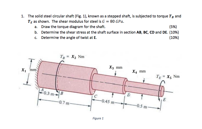
Solved X1 77mmx2 62mmx3 56 Mmx4 36mmx5 33 N M T
I'm almost embarrassed at posting this but I'm struggling to wrap my head around this. I have a hollow shaft which I need to shear between 65 and 75 ft-lbs. Internal diameter at the shear point is .200" and the notch is a full radius groove. The diameter of the groove is what I need to calculate. This is the simplified description of the shaft: Shaft OAL is 5.5" There are 2 milled hexes on each end and the center of the groove is 1" from one of the ends. Material is Nitralloy 135M. Woul...

The Solid 50 Mm Diameter Shaft Is Used To Transmit The Torque Applied To The Gears As Shown In The Figure Below Determine The Absolute Maximum Shear Stress In The Shaft
2. Understanding Language Language is Process Understanding language (not ” a” language) means understanding the processes that produce it. Language really only exists as production incidents and there records. By understanding language here we mean essentially understanding linguistic behavior. In particular we mean the processes of linguistic behavior both on the generative side and the reception side. There is no language independent of these processes. There may be records...

A Solid 0 75 In Diameter Shaft Is Subjected To The Torques Shown In Figure P6 8 The Bearings Shown Allow The Shaft To Turn Freely A Plot A Torque Diagram Showing The Internal Torque In
23:05EAS212_Lecture 6 - Supplement 4 (Internal Torque Diagrams). 5,723 views5.7K views. Jan 25, 2015. 98. 0 ...26 Jan 2015 · Uploaded by Evan Kristof

Strain Gauge Based Torque Sensors Measurement Experts Datum Electronics
Creating a new post to update [this one from a few weeks ago](https://www.reddit.com/r/BMWi3/comments/mpe1cc/my_rex_ice_died_getting_replaced_under_cpo/). There was a lot of interest as to what exactly went mechanically wrong. **Short version:** * My 2017 REx gas engine stopped working, out of the blue * 40k total miles, probably around 5k miles of REX driving * **Dealer replaced the entire REx engine after finding debris in the oil that apparently stuck to a magnet.** Per my previous post's ...
Internal Torque Diagram Exam Question F13 Chokeberry Youtube
**Main** **Engine** **: Uljanik-Man** **B&W** · **Main** **Engine** **Make** **:** Uljanik-Man B&W, **Type** **:** **6L60MC** No. of Cylinder : 6, Power : 10440 Kw, Rpm : 117, Mep : 16.2 Bar, Engine No. : 286, Year : 1989 **# Turbocharger Make :** BBC, **Type : VTR-564 (No Plate)** **#** **Governor Make** **:** Hydraulic Systems **#** **Oil** **Mist** **Detector** **Make** **:** Visatron (Schaller Automation), **Type** **:** **VN** **215/87** **PLUS** Art No. : 11851, Sr. No. : ...

Synthetic Bending Force Diagram And Torque Diagram Of Shaft C Download Scientific Diagram
6:50... Ends - Solution Beings 3:21 - Step Two - Repeat the process for BC, CD and DE4:47 - Step Three - Draw a ...21 May 2016 · Uploaded by AF Math & Engineering
Mechanics Map Axial Force Diagrams And Torque Diagrams
Produce a torque diagram. Locate the section(s) on the shaft where the combined internal loading is the highest..This important stage requires significant effort and judgement; Assess the strength of the shaft and determine if the safety margin is sufficient.

Question 1 10 Marks For The Circular Steel Shaft Subjected To Torque As Shown In Figure 1 Draw The Torque Diagram For The Shaft And Find The Course Hero
[#windturbine](https://engine.presearch.org/search?q=%23windturbine) [Wind turbine | wkpd](https://en.wikipedia.org/wiki/Wind_turbine) What with the frenzy over non-carbon energy sources, wind energy is having an uptrend. Today we're playing with what has become a [standard model](https://duckduckgo.com/?t=lm&q=common+wind+turbine+design&ia=web) (null hypothesis). Null-hyp turbines are specifically horizontal, [axial](https://en.wikipedia.org/wiki/Axial_turbine), 3-blade ([variable pi...

Suneducationgroup Com Business Office Industrial Mechanical Couplings U Joints D25l30 Shaft Coupler Flexible Coupling Cnc Stepper Motor For 3d Printer All Bore
Readers (if indeed there are any left) may recall that I have a 1979 Honda 400 engine in parts. I’ve done the work I originally dismantled it for and am now reassembling it - very slowly and cautiously. It’s a parallel twin and has a chain driven balancer mechanism to smooth out the engine. I’ve had all sorts of fun trying to get the balancer setup correct. Last time I did it the crank was really hard to turn and as I had forgotten to replace a seal anyway, I took it apart to redo. My first act...
3 Torsion Ppt Download
The "Torque Sequence" column shows which diagram to use as the specific bolt torquing sequence for your engine . All diagrams can be found in numerical sequence at the back of this publication .
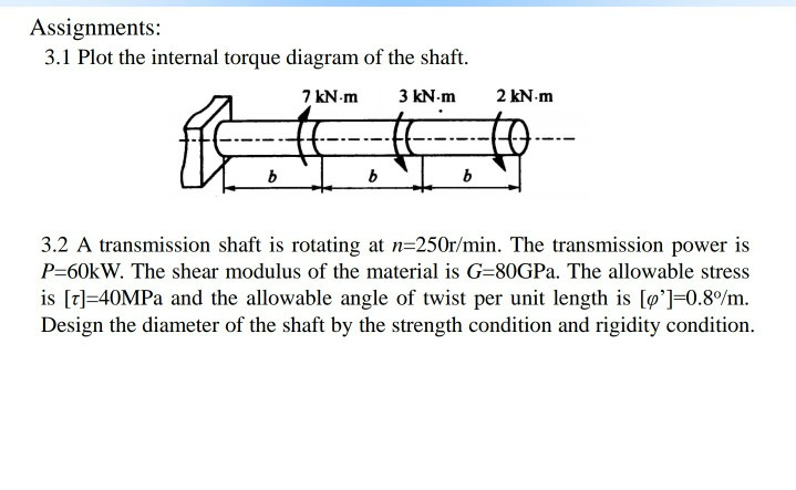
Solved Assignments 3 1 Plot The Internal Torque Diagram Of Chegg Com
T na Tne Torque In the shaft between the gears, 2400 (0.3/2Y 360 N.m Generate shear-moment diagrams for two planes. 360 28 2 422 — 1439 8822 3331 X N N Solution Perform free body diagram analysis to get reaction forces at the bearings. By = 422 N
Solution To Problem 323 Torsion Strength Of Materials Review At Mathalino
Shaft Analysis Engineering Library

Synthetic Bending Force Diagram And Torque Diagram Of Shaft D Download Scientific Diagram

Create Torque Diagram For Pulley Shaft Design

Find Internal Resisting Torque Of Each Segment Of Shaft Under Multiple Torques Make Torque Diagram Youtube

Solved Distributed And Concentrate Torsion Loadings On A Steel Shaft 1 Answer Transtutors
Asme Shaft Design Allowable Stress And Diameter Equations And Calculators Engineering Reference And Online Tools

Shaft Torque An Overview Sciencedirect Topics

Edge

Flywheel And Shaft Torque Analysis Engineering Reference And Online Tools
Torsional Stress Part2 Free Body Diagram And Examples Youtube
0 Response to "40 torque diagram for shaft"
Post a Comment