40 lewmar windlass wiring diagram
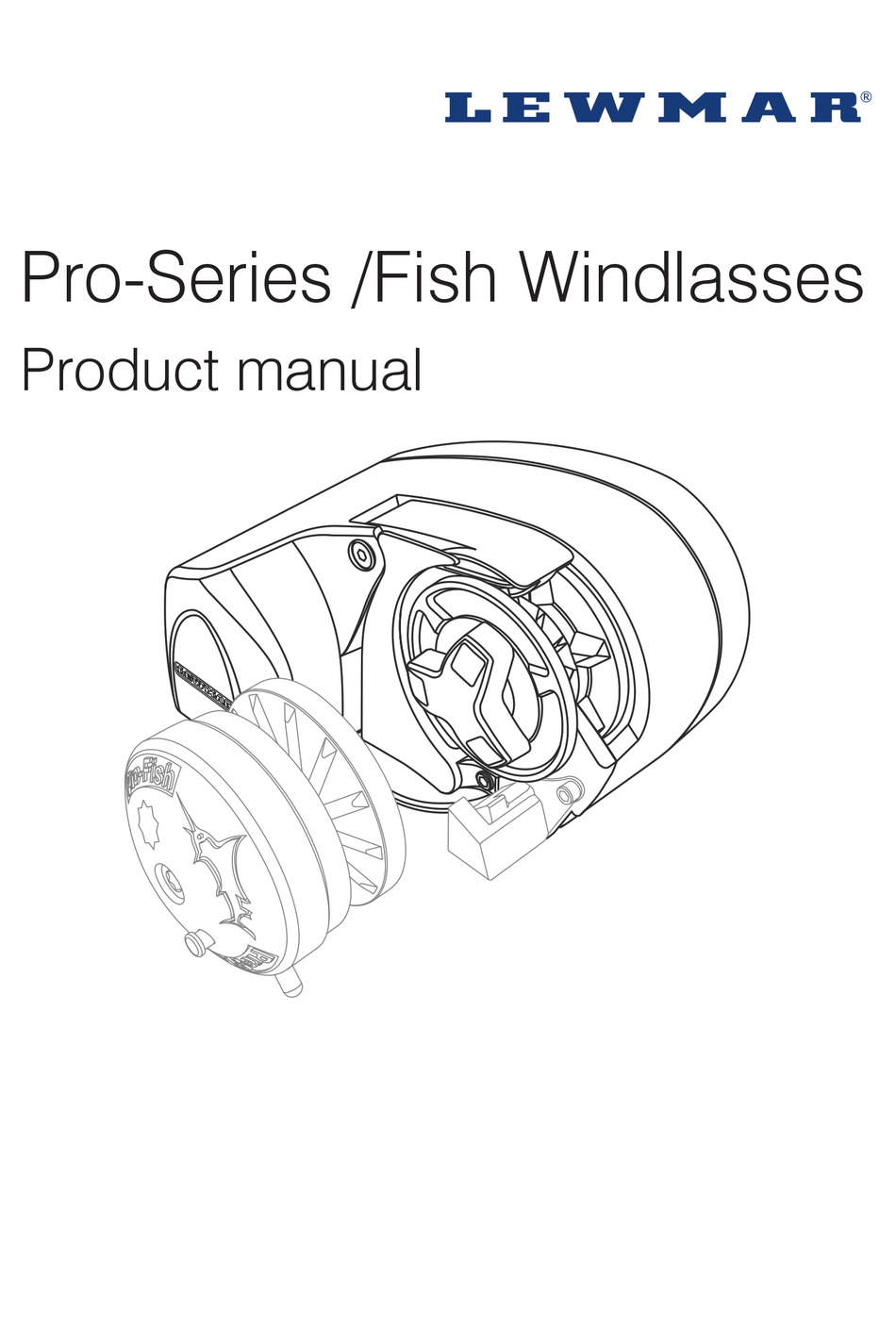
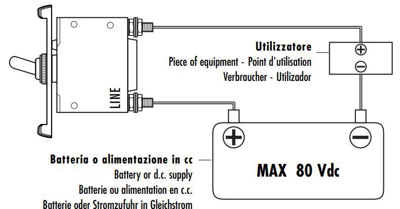
Lewmar Windlass Wiring Diagram Upgrade Windlass Power Wiring. Lewmar 2011 Catalog By Marinerparts Com Issuu. Lewmar Windlass Wiring The Hull Truth Boating And Fishing. Tigres 1500w 24v Horizontal Electric Windlass Lw415an 1. Lewmar Windlass Pro Fish Stopper Kit. Pro-Series Windlass. Owner's Installation, Operation & Service Manual. Contents. 1. Exploded Diagram. Overload protection, in the form of the circuit breaker/isolator supplied, must be built into the windlass wiring circuit. This protects the wiring and prevents undue damage to the windlass...
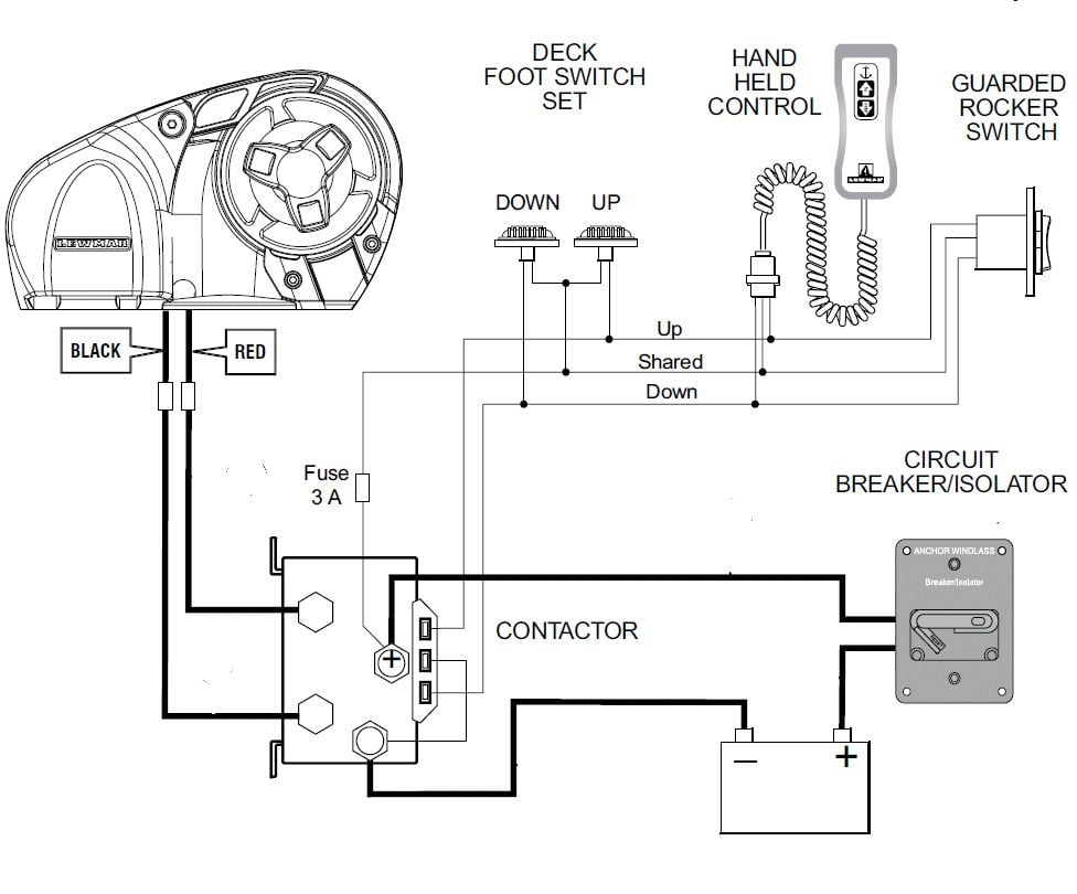
Lewmar VX1 Vertical Windlass 65100045.Iss 8 11. Optional Wire-less Control. Available(See § 5.3) ON. 4.8 VX1l - Wiring diagram if a contactor box (Part No 68000965) is used. Installation instructions are supplied separately with any accessories.

Lewmar windlass wiring diagram
Windlass Wiring Diagram - Your windlass motor is running but the chainwheel doesn t turn. Mako 1500 low profile windlass boats up to 65 ft. A wiring diagram is a streamlined standard pictorial depiction of an electrical circuit. Lewmar windlass solenoid wiring diagram 10 09 2018 10 09 2018... From americas cup racers mega yacht captains to recreational cruisers lewmar has got your back. 200mm 8 one touch power grip winch h... Lewmar windlasses are designed and supplied for anchor control in marine applications and are not to be used. 5.4 V1-6 Wiring diagram. Installation instructions are supplied separately with any accessories. 1. NOTE: Motor connections D1 = F1 D2 = F2 2. Switch wire thickness: 1.5 mm2 (16...
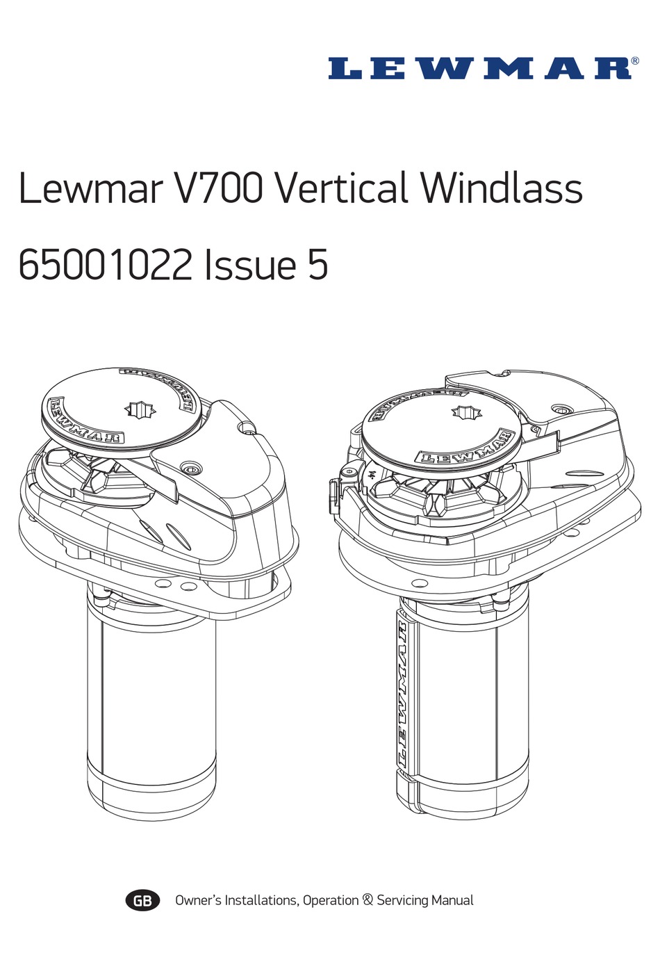
Lewmar windlass wiring diagram. Lewmar CPX Vertical Windlass 66300104 Iss. 7. GB Owners Installations, Operation & servicing manual. Dear Customer, Thank you for choosing Lewmar. Lewmar products are world renowned for their 4.5 Wiring diagram CPX 1-3 & 5. Installation instructions are supplied separately with any... 5.4 V700 Wiring diagram (toggle switch). Choice of cable thickness depends on total cable length: A+B+C+D+E= Battery to windlass, windlass to battery. El Rode debe hacerse rápido directamente a un bolardo, puesto Sampson o cornamusa. Lewmar V700 Vertical Windlass ref 65001022 iss.8. Lewmar Wiring Diagram Wiring Diagram Third Level. 66840008 Lewmar Bow Roller For Delta Type Anchors 14lb To 35lb. Lewmar Windlass V700 Kit 1 4 In G4 Chain Rope Gypsy 12v. Vertical Windlass Diagram Courtesy Of Lewmar This Diagram. Vetus Bow Thruster Control Wiring Diagram 2014... Lewmar Windlass Wiring Diagram Source: schematron.org. Before reading the schematic, get common and understand all the symbols. Typically the above tips as well as check not merely aid in safe power wiring changes as well as replacements but likewise pave a approach for safer homes.
• Lewmar windlasses are designed and supplied for anchor control in marine applications and are not to be used in conjunction with any other use. 5.4 V700 Wiring diagram (toggle switch). Choice of cable thickness depends on total cable length: A+B+C+D+E= Battery to windlass, windlass to battery. Easy anchoring starts with a Lewmar windlass. Whether you own a small fishing boat, a 160ft cruiser or a mid-size sailboat, Lewmar has a windlass designed to fit your exact needs. Each one is crafted with durability, convenience and affordability in mind. Both our vertical and horizontal designs are... 4.6 Wiring diagram if a pre-wired control box (Part No 68000963) is used. Installation instructions are supplied separately with any accessories. anchor. Note: If the clutch nut is not tight the internal clutch will rotate freely and not engage the drive. Lewmar HX1 Horizontal Windlass - 65140050 Iss.2. Page 9 5.6 Wiring diagram if a pre-wired control box (Part No 68000963) is used Installation instructions are supplied separately with any accessories. Lewmar Pro-Series/Fish windlass ref B10414 iss.1... Page 10 2. Release any anchor locks 3.When safe insert the Lewmar wrench in to the...
Windlass Wiring Diagram Wiring Diagram Official. Standard Winch Size 43 Lewmar. Buy Lewmar Windlass V700 Kit 1 4g4 In Usa Binnacle Com. Lewmar Windlass Wiring Diagram. At lewmar we think about what makes boaters lives easier and bring those ideas to life in our products. Wiring diagrams must be followed without modification. Using a 10 mm 38 diameter drill make the three holes for the mounting studs. Lewmar Windlass Wiring Diagram from images-na.ssl-images-amazon.com. Effectively read a wiring diagram, one provides to find out how the components within the method operate. For example , if a module will be powered up and it also sends out a signal of half the voltage in addition to the... Lewmar windlasses are designed and supplied for anchor control in marine applications and are not to be . Wiring diagram using contactor provided ( Part No ) .. Pre & Custom Build Models. Can be used with all Lewmar custom windlasses, contact the sales office for a specific wiring diagram.
Lewmar windlasses are designed and supplied for anchor control in marine applications and are. not to be used in conjunction with any other use. • 5.6 Wiring diagram if a pre-wired control box (Part No 68000963) is used Installation instructions are supplied separately with any accessories.
2.1 Windlass general 2.2 Fitting 2.3 Electrical. 4.1 Electric cable selection 4.2 Wiring 4.3 Control switch installation 4.4 V1-6 wiring diagram. Lewmar V1, V2, V3 & SPORT Windlass | 3. 1. Introduction. Dear Customer, Thank you for choosing Lewmar.

Concept 3 Windlass Appears Dead I Can Hear A Solenoid Clicking Under The Deck But No Life In The Motor Voltage At
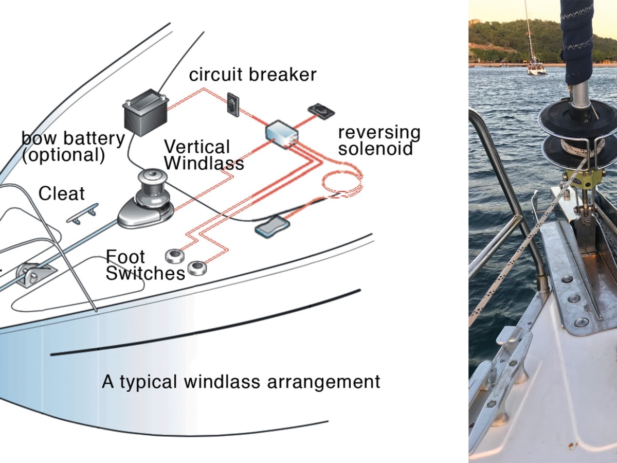
Planning the installation 3. 20+ Simpson Lawrence Windlass Wiring Diagram Pictures. 1 16 of 88 results for lewmar windlass parts skip to main search results amazon prime. Installing a new electric windlass part 2. Operating your windlass 9 3 1 safety fi rst 9 3 2 use of clutch 9 3 3 letting go under...
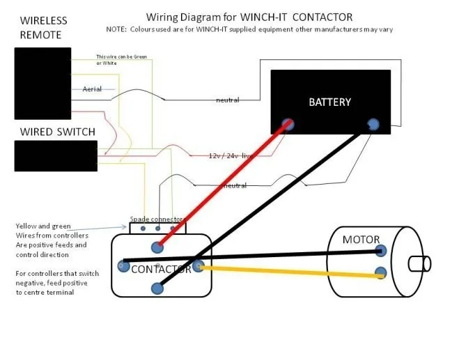
12v Winch Solenoid Relay Controller 500a Dc Switch 4wd 4x4 Boat Atv Control For Jeep Bmw Benz Audi Peugeot Vw Seat Lada Toyota Winch Solenoid 12v Winch Solenoid4wd Switch Aliexpress
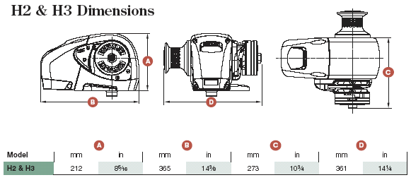
1. Windlasses. Lewmar Anchor Windlass Range. Page 10 Captive Reel Windlass. Dimensions Diagram. Control arm kit: 66810030. Manual recovery kit. The integral contactor simplifies wiring and is protected by a durable maincase.
3.1 Windlass general. At all times it is the responsibility of the boat user to ensure that the anchor and rode are properly stowed for the prevailing sea Visit www.lewmar.com for more information Contactor box used in some installation refer to wiring diagram § 5.5 and § 5.6 Optional wireless remote also...
This is part 2 of our video series on how to install your Lewmar V700 windlass. If you've missed the first part, you can find it here...
Windlass wiring diagram (Fig 1). 1. RED-Connect to Positive of 12/24 VDC supply via a 5A fuse 2. BLACK-Connect to 0V of a power supply 3. ORANGE-Programming wire, leave disconnected, see. Wireless Control System. Danke schön für den Erwerb eines drahtlosen Lewmar Control Systemes. •
Get inspired with Lewmar Windlass Wiring Diagram images on Wiring Diagrams Image Source, Browse inspirational photos on JPG, PNG, BMP and Lewmar windlasses are designed and supplied for anchor control in marine applications and are not to be used. 17 Always keep hands and feet clear...
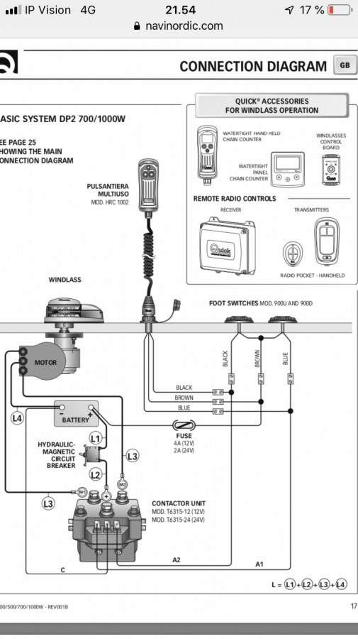
Quick Windlass Wiring Diagram - Wiring Diagram from jimmygreen.com. Before removing any wires either label them or draw a diagram . 5.4 wiring diagram using contactor provided (part no 68000939). Page 8 5.4 v700 wiring diagram (toggle switch) choice of cable thickness depends on total cable...
American Standard Furnace Wiring Diagram . House Wiring Diagram Pdf . Diagram Diagramsample Diagramtemplate Wiringdiagram.
2. Electrical wiring installation 2.1 Electric cable selection 2.2 Wiring 2.3 Control switch installation 2.4 V700 Wiring diagram (toggle switch) 2.5 V700 However, Lewmar cannot. accept liability for any inaccuracies or omissions it may contain. 9 In addition, our policy of continuous product improvement...
Lewmar Windlass Wiring Diagram The Lewmar Pro-Series range of windlasses are DIY-ready, easy to install and housed in 100% 316 stainless steel. The durable deck unit with closed cell neoprene gasket keeps the internal parts well protected. Lewmar Pro Sport 550 Manual.
Lewmar windlasses are designed and supplied for anchor control in marine applications and are not to be used. 5.4 V1-6 Wiring diagram. Installation instructions are supplied separately with any accessories. 1. NOTE: Motor connections D1 = F1 D2 = F2 2. Switch wire thickness: 1.5 mm2 (16...
From americas cup racers mega yacht captains to recreational cruisers lewmar has got your back. 200mm 8 one touch power grip winch h...
Windlass Wiring Diagram - Your windlass motor is running but the chainwheel doesn t turn. Mako 1500 low profile windlass boats up to 65 ft. A wiring diagram is a streamlined standard pictorial depiction of an electrical circuit. Lewmar windlass solenoid wiring diagram 10 09 2018 10 09 2018...

Lewmar Windlass Wiring Diagram Upgrade Windlass Power Wiring Of Lewmar Windlass Wiring Diagram With Windlass Wiring Diagram For Windlas Diagram Power Wire Wire

Electrical Switches Anchor Windlasses Lewmar Vertical Anchor Windlass Lewmar V700 Vertical Windlass Rocker Switch Guard Angle Electronics Png Pngegg










0 Response to "40 lewmar windlass wiring diagram"
Post a Comment