40 iron carbon ttt diagram
Using the TTT diagram for an iron-carbon alloy of eutectoid composition as shown in the figure below, specify the nature of the final microstructure (in terms of phases present and approximate percentages of each) of a small specimen that has been subjected to the following time-temperature treatments. In each case assume that the specimen begins at 800°C and that it has been held at this ... The effects of carbon on certain characteristics of pure iron are shown in Fig. 3 (Ref 3). Figure 3(a) is a simplified version of Fig. 1; that is, a straight line constitutional diagram of commercially pure iron. In Fig. 3(b), the diagram is expanded horizontally to depict the initial effects of carbon on the principal thermal points of pure iron.
For reference, here’s the relevant portion of the iron-carbon phase diagram. First, heat the alloy to 30-50°C higher than the critical temperature. This region is labelled in the diagram above. We don’t want to stay at this temperature for long, because it might cause grain growth. If you are working on an alloy that is sensitive to oxidation, you may want to heat the alloy in a vacuum ...

Iron carbon ttt diagram
the iron-carbon alloy system. A sample of the eutectoid composition is cooled from a single-phase region (γ) to a temperature (T) below the eutectoid temperature (T E). The following diagram shows a part of the iron-carbon phase diagram. Concentrations C 1, C 2, C 3, C 4 are various equilibrium ( stable as well as metastable ) concentrations ... TTT Diagram For Eutectoid Steel ( Isothermal Transformation Diagram ) Time-Temperature-Transformation ... We have seen that the iron-carbon phase diagram does not show time as a variable and hence the effects of different cooling rates on the structures of steels are not revealed. Moreover, equilibrium conditions are not maintained in heat treatment. Although, the iron-carbon equilibrium ... 1) Equilibrium phase diagrams, Particle strengthening by precipitation and precipitation reactions 2) Kinetics of nucleation and growth 3) The iron-carbon system, phase transformations 4) Transformation rate effects and TTT diagrams, Microstructure and property changes in iron-carbon system Contents
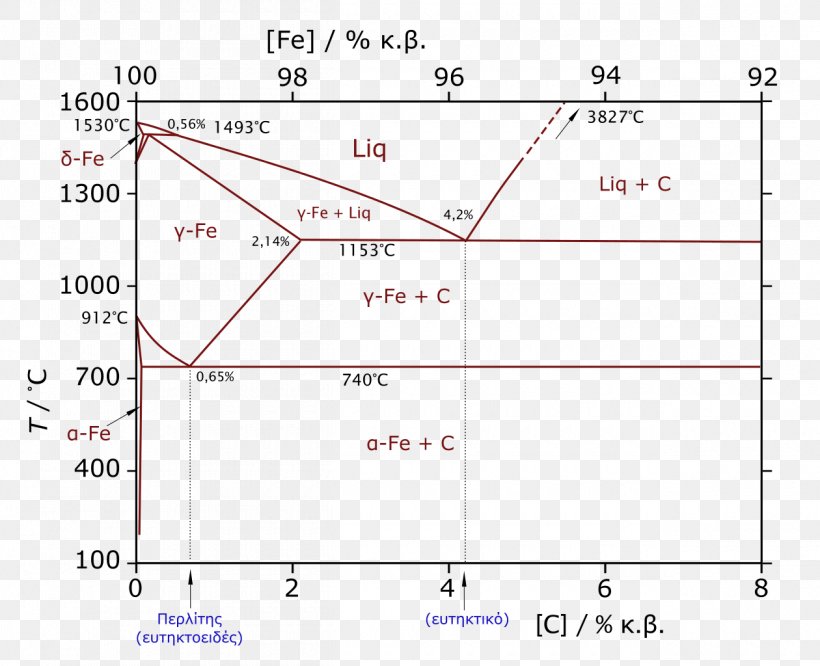
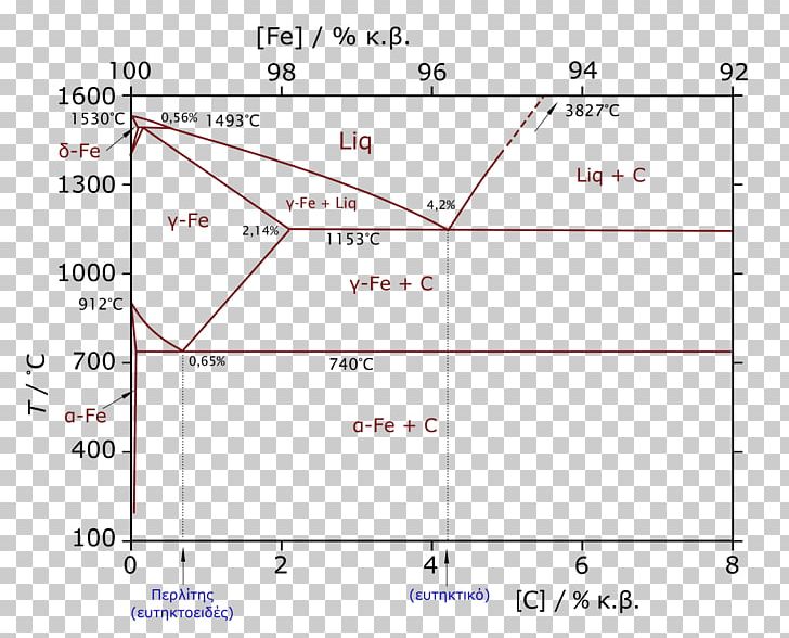
Iron carbon ttt diagram. Time-temperature-transformation (TTT) diagram Jul 07, 2021 · White Heart Cast Iron. In oxidizing atmosphere, all graphite will be oxidized. With annealing at 900 o C, all iron carbide is decomposed into iron and carbon. This nodular iron from surface will be oxidized by removing carbon from surface. Black Heart Cast Iron. Cast iron types developed in Cupola contains interspersed graphite nodules with ... Thermodynamic temperature is a quantity defined in thermodynamics as distinct from kinetic theory or statistical mechanics.A thermodynamic temperature reading of zero is of particular importance for the third law of thermodynamics.By courtesy, it reported on the Kelvin scale of temperature in which the unit of measure is the kelvin (unit symbol: K). The Fe - C diagram (also called the iron - carbon phase or equilibrium diagram) is a graphic representation of the respective microstructure states of the alloy iron - carbon (Fe-C) depending on temperature and carbon content. To explain this diagram, an introduction about metal structures and pure iron must be done.
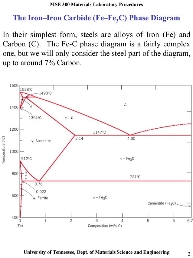
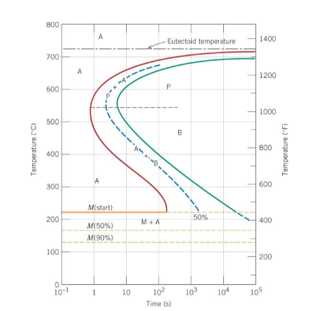
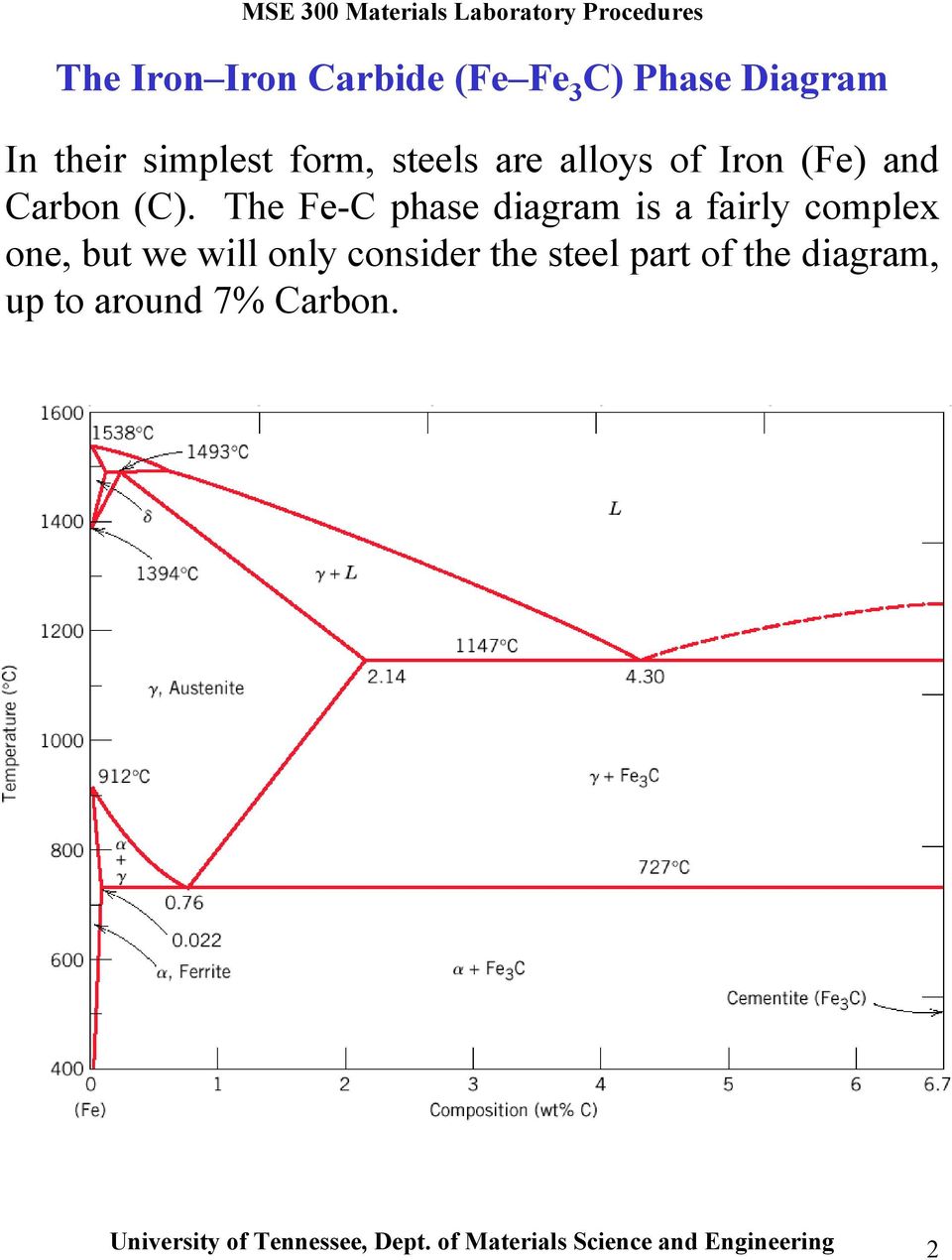
Factors affecting TTT diagram Composition of steel- (a) carbon wt%, (b) alloying element wt% Grain size of austenite Heterogeneity of austenite Carbon wt%- As the carbon percentage increases A3 decreases, similar IS the case for A i.e. austenite stabilises. So the incubation period for the Explanation: TTT Diagram: The rate of phase transformation also depends upon the temperature.; Temperature-time-transformation diagram (TTT), also known as isothermal transformation curves, are useful in planning heat treatments. The complete isothermal transformation diagram for an iron-carbon alloy of eutectoid composition A (austenite), B (Bainite), M (Martensite), P (Pearlite) is below: The Iron-Iron Carbide (Fe-Fe3C) Phase Diagram In their simplest form, steels are alloys of Iron (Fe) and Carbon (C). The Fe-C phase diagram is a fairly complex one, but we will only consider the steel part of the diagram, up to around 7% Carbon. Bainite Formation Diagram. At 900 °C a typical low-carbon steel is composed entirely of austenite, the high temperature phase of iron. ... Ideal TTT-curve for 0,65% ...
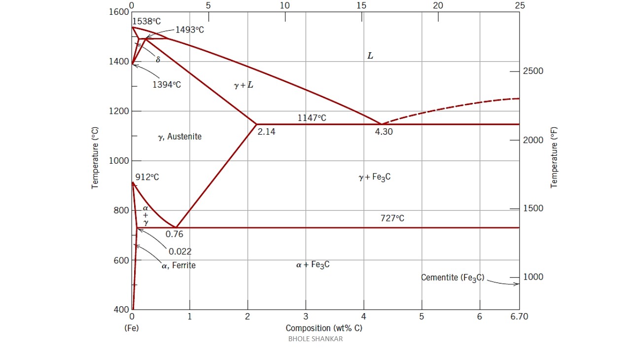
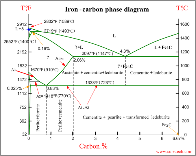
Iron -Iron-carbon diagrams provides the best medium to understand this aspect. The diagram provides the foundation knowledge on both plain carbon and alloy steels in a great variety. It must be noted that the normal equilibrium diagram actually is a metastable equilibrium diagram between iron and iron carbide (cementite). Transcribed image text: b. Use the TTT diagram for a 0.45 wt% C iron-carbon alloy below, to design a a heat treatment that could be used to isothermally convert a microstructure that consists of proeutectoid ferrite and fine pearlite into one that is composed of proeutectoid ferrite and bainite? The complete isothermal transformation diagram for an iron-carbon alloy of eutectoid composition. A: austenite , B: bainite , M: martensite , P: pearlite TTT diagram gives 1- Nature and type of transformation . 2- Rate of transformation. 3- Stability of phases under isothermal transformation conditions. This iron carbon phase diagram is plotted with the carbon concentrations by weight on the X-axis and the temperature scale on the Y-axis. The carbon in iron is an interstitial impurity. The alloy may form a face centred cubic (FCC) lattice or a body centred cubic (BCC) lattice. It will form a solid solution with α, γ, and δ phases of iron.
Iron Carbon Phase Diagram
Iron Carbon Ttt Diagram. TTT diagram is a plot of temperature versus the logarithm of time for a steel alloy of The complete isothermal transformation diagram for an iron-carbon alloy. Imagine, for example, some pure iron that was kept at a temperature of oC ( .. Here is the "official" isothermal TTT diagram for eutectoid carbon steel.
What Is The Difference Between An Iron Carbon And A Phase Diagram Quora
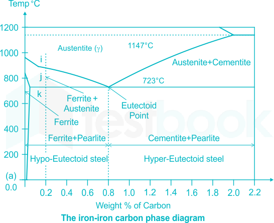
diagram shown in Figure 6-1. Steel with a 0.78 wt% C is said to be a eutectoid steel. Steel with carbon content less than 0.78 wt% C is hypoeutectoid and greater than 0.78 wt% C is hypereutectoid. The region marked austenite is face-centered-cubic (FCC) and ferrite is body-centered-cubic (BCC). There are also regions that have two phases. If one cools a hypoeutectoid steel from a point in the ...
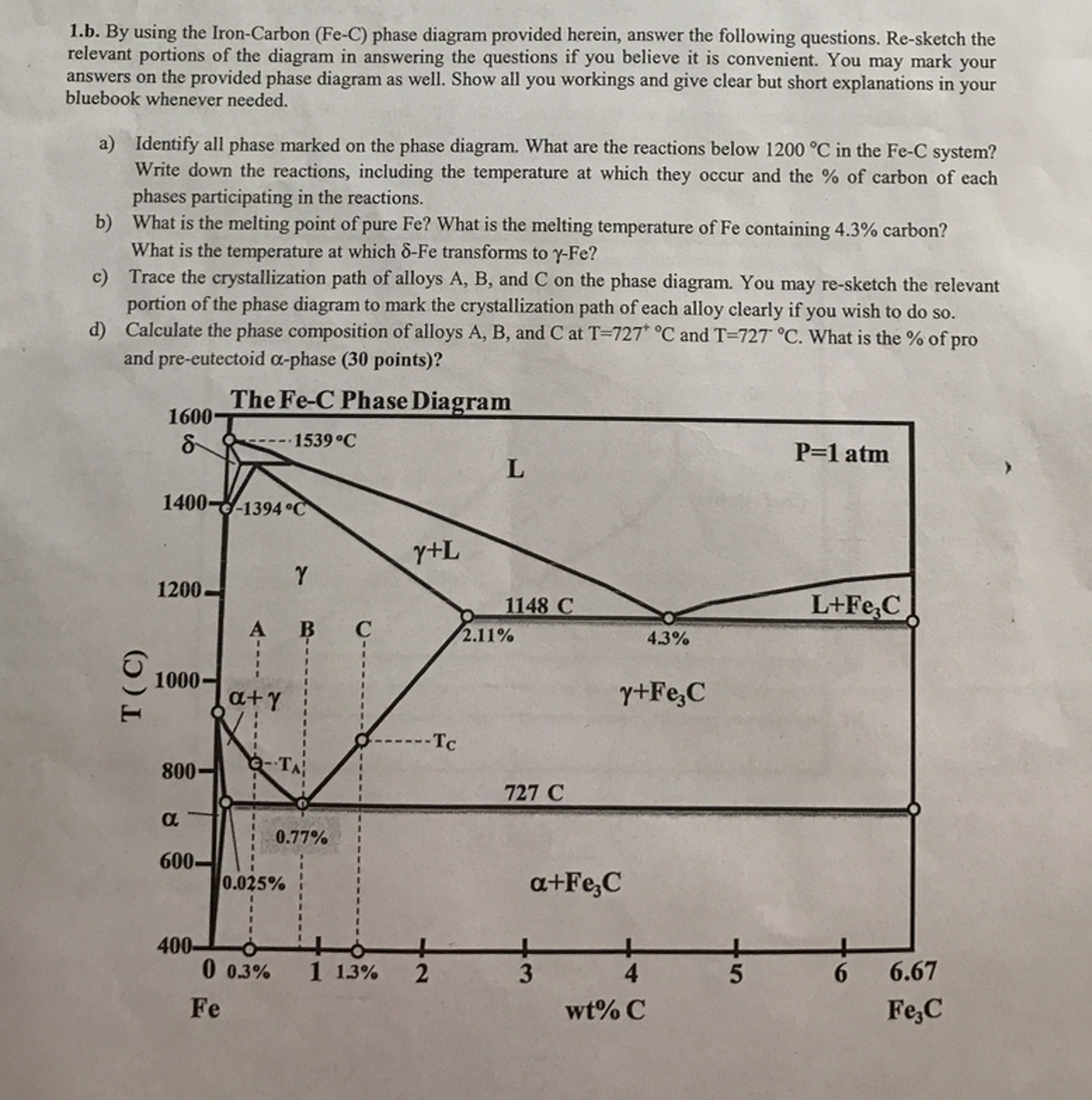
Solved By Using The Iron Carbon Fe C Phase Diagram Chegg Com
Fig. 4 shows the schematic TTT diagram for eutectoid plain carbon steel 8. Fig.4: Time temperature transformation (schematic) diagram for plain carbon eutectoid steel t 1 t 2 t 3 t 4 t 5 M F, Martensite finish temperature M 50, 50% Martensite M S, Martensite start temperature Metastable austenite +martensite Martensite e 0 100 e
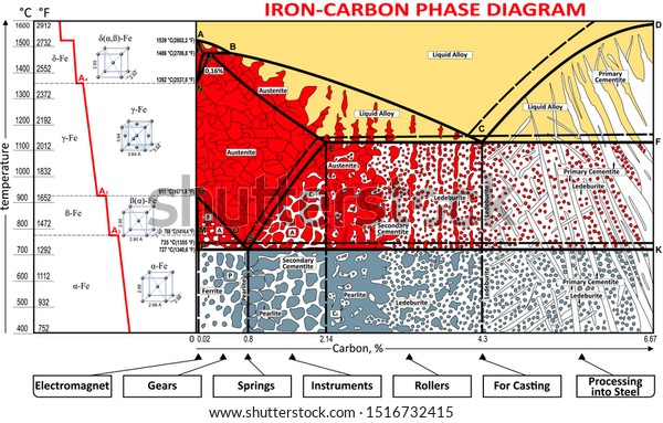
Vektor Stok Coloring Vector Ironcarbon Phase Diagram Tanpa Royalti 1516732415
Iron-Iron Carbide Phase Diagram - Callister. Austenite is a polymorph of iron, in a face centred cubic (FCC) structure. Carbon is relatively soluble in this phase (up to 2% C at 1100°C). It is therefore found in mild carbon steel above the eutectoid temperature of 727°C. As it cools, the austenite transforms into the much less carbon soluble ...

The Iron Iron Carbide Fe Fe C Phase Diagram Pdf Document
2. TTT - Diagrams 13 Different carbon solubility of solid solutions also results from lattice structures. The three a-bove mentioned phases dissolve carbon interstitially, i.e. carbon is embedded between the iron atoms. Therefore, this types of solid solutions are also named interstitial solid solution.

Iron Carbon Phase Diagram Pdf Document
asked Dec 29, 2017 in material science by chandu (215k points) Which one of the following statements is correct? (a) Iron-carbon and TTT diagrams are both equilibrium diagrams. (b) Iron-carbon and TTT diagrams are both non-equilibrium diagrams. (c) Iron-carbon diagram is an equilibrium diagram but TTT diagram is a non-equilibrium diagram.

The Iron Carbon Phase Diagram Metallurgical Engineering Facebook
SOLUTIONS MANUAL FUNDAMENTALS OF MODERN MANUFACTURING: MATERIALS, PROCESSES, AND SYSTEMS Second Edition
Solved The Iron Carbon Diagram And The Ttt Curves Are Determined Under Self Study 365
Why TTT diagram is c shaped? We have mentioned before, TTT diagram is time and temperature transformation diagram.Pearlitic transformation is a diffusion-based transformation which involves solid-state conversion into alpha iron and iron carbide colonies. Without the required temperature and time, diffusion is not possible, and structure will, then, have martensite or bainite transformations.
Solved In The Iron Iron Carbide Phase Diagram Of Figure 6 4 Identify The 1 Answer Transtutors
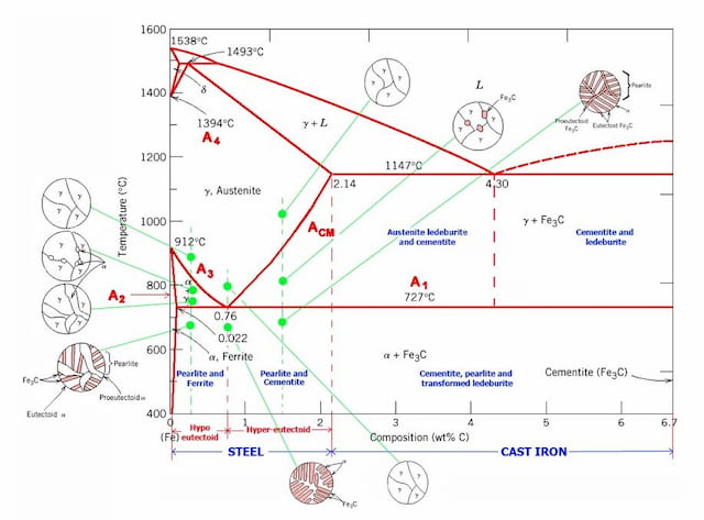
IRON CARBON EQUILIBRIUM DIAGRAM, TTT DIAGRAM AND HEAT TREATMENT 1. IRON CARBIDE DIAGRAM TTT DIAGRAM & HEAT TREATMENT By: Ankit Saxena 2. IRON-C phase diagram 3. From previous fig of FE-C diagram 4. • Hypo-eutectoid steels: Steels having less than 0.8% carbon are called hypo-eutectoid steels (hypo means "less than").
Iron Carbon Phase Diagram Graphite Png 1260x1024px Phase Diagram Alloy Area Carbon Cast Iron Download Free
10.18 Using the isothermal transformation diagram for an iron-carbon alloy of eutectoid composition (Figure 10.22), specify the nature of the final microstructure (in terms of microconstituents present and approximate percentages of each) of a small specimen that has been subjected to the following time-temperature treatments. In
2
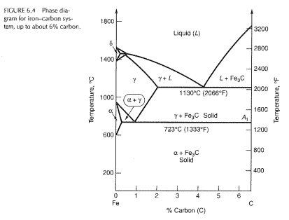
Nov 18, 2013 · Iron–Carbon Phase Diagram • In their simplest form, steels are alloys of Iron (Fe) and Carbon (C). • The Fe-C phase diagram is a fairly complex one, but we will only consider the steel and cast iron part of the diagram, up to 6.67% Carbon.

Please Answer The Following Question Regarding The Iron Iron Carbide Phase Diagram A Carefully Draw And Label The Phase Diagram Of Iron And Carbon Alloy Up To 6 Carbon Contents B For Pure
This video will provide you complete details about Time Temperature Transformation Curve & development of Non equilibrium Phases,Difference between Iron Carb...
Iron Carbon Phase Diagram Steemkr
TTT diagram indicates when a specific transformation starts and ends and it also shows what percentage of transformation of austenite at a particular temperature is achieved. Look at figure 1b and 1c. Figure 2. Upper half of TTT Diagram(Austenite-Pearlite Transformation Area) Figure 2 represents the upper half of the TTT diagram.

Iron Carbon Phase Diagram In Brief Engineering Insider
Time-temperature transformation (TTT) diagram. The red line shows the cooling curve for austempering. Austempering is heat treatment that is applied to ferrous metals, most notably steel and ductile iron. In steel it produces a bainite microstructure whereas in cast irons it produces a structure of acicular ferrite and high carbon, stabilized austenite known as ausferrite. It is primarily used ...
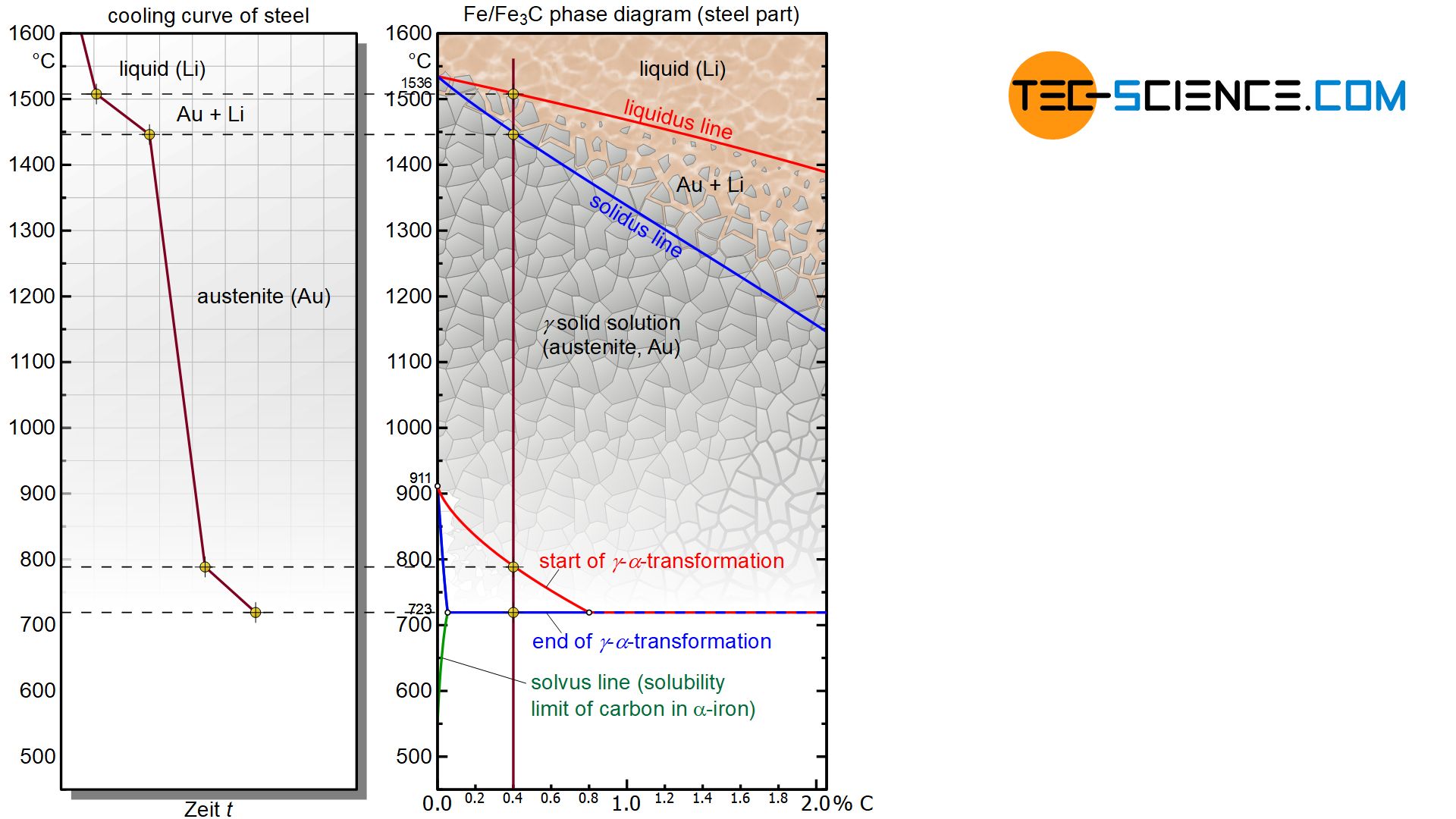
Microstructure Formation Of Steels During Solidification Tec Science
The CCT diagram (solid lines) for a 1080 steel compared with the TTT diagram (dashed lines). 67. ©2003 Brooks/Cole, a division of Thomson Learning, Inc. Thomson Learning ™ is a trademark used herein under license. (a)TTT and (b) (b) CCT curves for a 4340 steel. 68. Factors Affecting TTT Diagram • 1. Grain size • 2. Carbon content • 3.
Iron Carbon Phase Diagram Explained With Graphs
For plain carbon steel with carbon concentrations below 2 %, you needn't worry, indeed. Graphite is never formed and the usual phase diagram covers everything nicely. For cast-iron, with carbon concentrations up to a few percent you need to worry. Graphite might form, depending on conditions.

Iron Carbon Diagram Of Steel Pdf Pdf Iron Steel
Cementite or iron carbide, is very hard, brittle intermetallic compound of iron & carbon, as Fe 3 C, contains 6.67 % C. It is the hardest structure that appears on the diagram, exact melting point unknown. Its crystal structure is orthorhombic. It is has low tensile strength (approx. 5,000 psi), but high compressive strength.

Metastable Iron Carbon Fe C Phase Diagram Diagram Iron Steel Metal Working
The complete TTT diagram for an iron-carbon alloy of eutectoid composition. A: austenite B: bainite M: martensite P: pearlite Er. Saurabh Malpotra . TTT Diagram Transformations at temperatures between approximately 705°C and 550°C result in the characteristic lamellar microstructure of pearlite.

File Iron Carbon Phase Diagram Svg Wikimedia Commons
TTT diagram is a plot of temperature versus the logarithm of time for a steel alloy of The complete isothermal transformation diagram for an iron-carbon alloy.C metastable equilibrium diagram and TTT diagrams for plain carbon hypoeutectoid, eutectoid and hypereutectoid steels M S (a) Fe-Fe 3 C metastable phase diagram (b) TTT diagram for ...
Iron Phase Diagram Roy Mech
The diagrams that illustrate the transformation of austenite as a function of time at a constant temperature is a TTT, or isothermal transformation (IT) diagram. In the simplest form (in plain carbon, or low alloy steels), these curves have a well-defined 'C' or 'S' shape.

Iron Carbon Phase Diagram Pdf Alloy Steel
Somewhere on your IRON -carbon diagram is the word "equilibrium" ; It describes equilibrium conditions. TTT curves are sort of the antithesis of equilibrium ; The right hand boundary is static conditions. But the route or path taken to get to the right boundary makes a substantial difference in what you have when you get there .

Iron Carbon Phase Diagram Diagram Quizlet
1) Equilibrium phase diagrams, Particle strengthening by precipitation and precipitation reactions 2) Kinetics of nucleation and growth 3) The iron-carbon system, phase transformations 4) Transformation rate effects and TTT diagrams, Microstructure and property changes in iron-carbon system Contents
Steels An Introduction To Heat Treatment
TTT Diagram For Eutectoid Steel ( Isothermal Transformation Diagram ) Time-Temperature-Transformation ... We have seen that the iron-carbon phase diagram does not show time as a variable and hence the effects of different cooling rates on the structures of steels are not revealed. Moreover, equilibrium conditions are not maintained in heat treatment. Although, the iron-carbon equilibrium ...

Iron Carbon Steel Phase Diagram Malzeme Bilimi Kimya Makine Muhendisligi
the iron-carbon alloy system. A sample of the eutectoid composition is cooled from a single-phase region (γ) to a temperature (T) below the eutectoid temperature (T E). The following diagram shows a part of the iron-carbon phase diagram. Concentrations C 1, C 2, C 3, C 4 are various equilibrium ( stable as well as metastable ) concentrations ...

The Iron Carbon Phase Diagram
Iron Carbon Phase

The Iron Carbon Equilibrium Diagram Total Materia Article
A Temperature Stress Phase Diagram Of Carbon Supersaturated Bcc Iron Exhibiting Beyond Zener Ordering Springerlink
2

Iron Carbon Phase Diagram In Their Simplest Form Steels Are Alloys Of Iron Fe And Carbon C The Study Of The Constitution And Structure Of Iron And Steel Start With The Iron Carbon

The Iron Carbon Phase Diagram
Iron Carbon Phase Diagram 12 Download Scientific Diagram
Iron Carbon Phase Diagram Graphite Png Clipart Alloy Angle Area Carbon Cast Iron Free Png Download
Iron Carbon Phase Diagram Substech

Phase Diagrams Ttt Plots Cct Diagrams Beng Project
Examples Of Iron Iron Carbide Transformations

The Iron Carbon Alloys And Fe C Phase Diagram Mechanicalbase
Solved B Ttt Diagram 2 Using The Isothermal Transformation Chegg Com
Iron Carbon Phase Diagram A Review See Callister Chapter 9 Pdf Free Download

The Iron Carbon Phase Diagram 46 Download Scientific Diagram
0 Response to "40 iron carbon ttt diagram"
Post a Comment