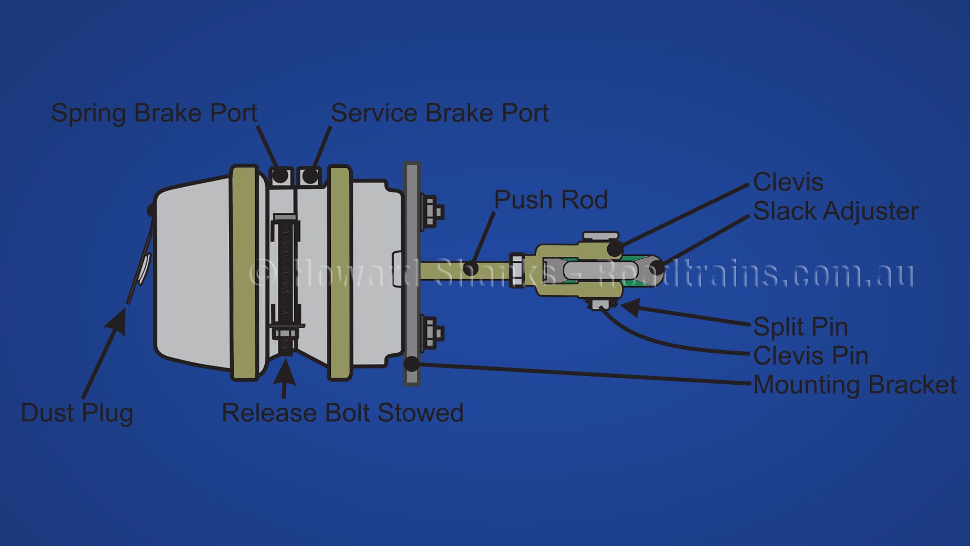
40 air brake chamber diagram
Troubleshooting the Model 'A' by TERRY OBERER 3609 Traci Lane Byrnes Mill, MO 63051-1047 Phone: 636-677-7201. Notes to audience: My name is Terry Oberer and have been driving Model "A's" since I was old enough to get a driver's license. The five main components of an "elementary" air brake system and their purposes are the compressor, reservoir, foot valve, brake chambers, and brake shoes and drums or brake rotors and pads.. You must have an Endorsement A specified on your licence to operate a vehicle equipped with an air brake system. The endorsement is not required when operating a Class 3 or 5 vehicle licensed as a ...
hydraulically or with air. Air brakes are similar in some ways to hydraulic brakes except that compressed air is used to actuate the brakes instead of brake fluid. The potential energy of an air brake system is from compressed air. The force delivered to the wheels has nothing to do with the pressure applied to the brake pedal.
Air brake chamber diagram
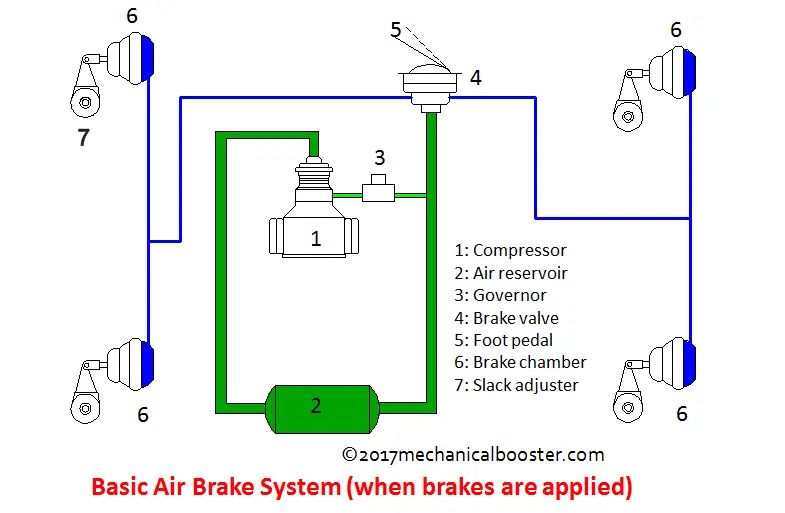
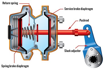
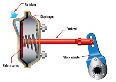
Each air brake chamber contains a pressure bleed valve and a push rod. The push rods have a spring return on the interior and a pressure plate the spans the width and depth of the chamber. When the brake pedal is depressed, air from the compressor is pumped into the chamber. This drives the push rod out with upwards of 1,000 pounds of force. Air intake snorkel ducts were first used in '75. All '75-'79 6-cyl engines had a plastic duct/tube connecting the air cleaner snorkel to the oval shaped hole in the inner edge of the driver side fender. '75 V8's had a similar setup with a flexible duct hose connecting to the oval shaped hole in the inner edge of the passenger side fender. Many good image inspirations on our internet are the very best image selection for Freightliner Air Brake System Diagram. . If you should be satisfied with some pictures we provide, please visit us this website again, don't forget to talk about to social media you have. Please see more wiring amber you will see it in the gallery below. .
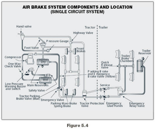
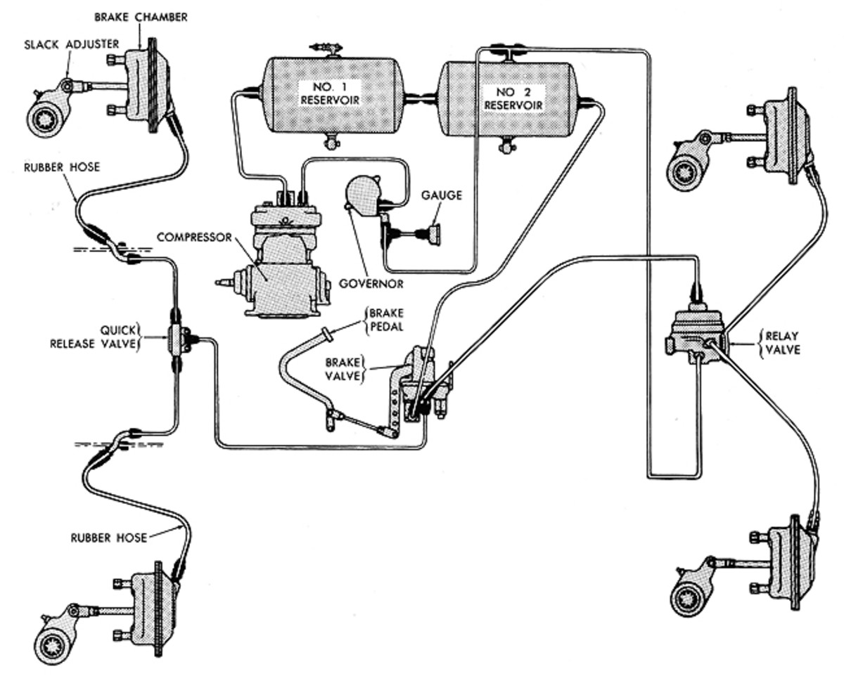
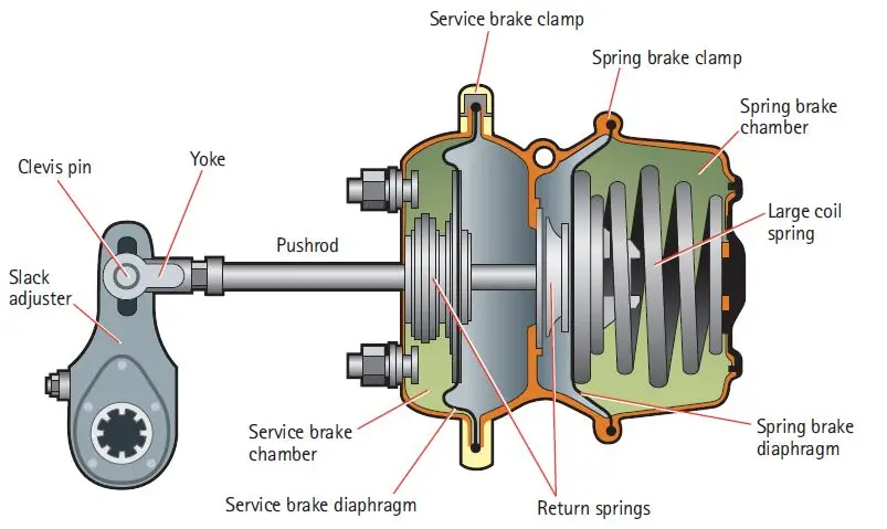
Air brake chamber diagram. Home » Wiring Diagrams » Brake Chamber Diagram. Tractor Trailer Air Brake System Diagram. Applsci 07 g001. 2012 02 12 2 12 2012 4 24 29 pm. We collect lots of pictures about Brake Chamber Diagram. and finally we upload it on our website. Many good image inspirations on our internet are the best image selection for Brake Chamber Diagram. brake chambers and applies force to the push rod, transferring the force to the SCam or air disc brake. (See page 19 for more about foundation brakes.) Frictional forces slow the wheels and the vehicle comes to a stop. When the brakes are released, the air in the brake chambers is able to be quickly rel eased and enable the vehicle to drive away. brake chamber (see Figure 5-2). Air pressure pushes the rod out, moving the slack adjuster, thus twisting the brake cam shaft. This turns the s-cam (so called because it is shaped like the letter "S"). The s-cam forces the brake shoes away from one another and presses tegrity of the air brake system. Motor Vehicle Safety Standards (MVSS) 121 requires an air capacity 12 times the total vol-ume of all air brake chambers on the vehicle. For additional information on calculating total air volume and brake chamber rated air volumes, refer to Liftable Axle Air System Requirements section in this bulletin.
Air Brake Endorsement • Permits the holder to drive vehicles equipped with air brakes in class of vehicle for which the driver is licenced. • To adjust manual or automatic slack adjusters, the operator must hold an "S" brake endorsement. Requirements for Air Brake Endorsement • Must complete an Air Brake Written Test. the rear brake chambers. At the same time, air is also drawn from the secondary reservoir, passes through the foot valve and is passed on to the front brake chambers. If there is air loss in either circuit, the other will continue to operate independently. For the BMW 5 E60, E61 2003, 2004, 2005, 2006, 2007, 2008, 2009, 2010 model year. Locate fuse box. In glove compartment. 1. Release both quick-release fasteners. 8 SAAP-CABCP03A2TLET 3 OFAAS BRAKE CHAMBER COMPONENTS (con't) SAP30241L Release Stud Assembly Type 30 For 2424L & 3030L SAP30242L Clevis Assembly with Pin Type 24 & 30 For 1024L,
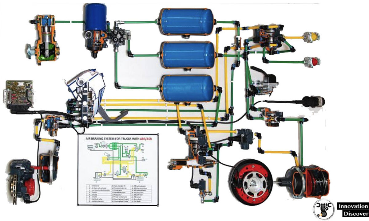
Typical 6 Wheel Air Brake System. These diagrams are provided for basic identification only. Always consult a professional technician to properly troubleshoot your system. Typical 10 Wheel Brake System. These diagrams are provided for basic identification only. Always consult a professional technician to properly troubleshoot your system. This video gives a detailed overview of the various components of service chambers and spring brakes. We identify long stroke, standard stoke, and different ... Standard Clamp Type Brake Chamber Type Adjustment Limit Type Adjustment Limit 9 1-3/8" 24 1-3/4" 12 1-3/8" 30 2" 16 1-3/4" 36 2-1/4" 20 1-3/4" DD-3 2-1/4" NOTE: Long stroke chambers are identified with square air ports or port bosses and special trapezoid ID tags. Long Stroke Type Brake Chamber Type Adjustment Limit Type Adjustment Limit -Brake drum out of round.-Brake chamber diaphragm failure.-Wrong brake lining.-Broken slack adjuster or foundation brake parts. 8.) Air Pressure Will Not Rise To Normal-Faulty air gauge (registering incorrectly).-Excessive valve or fitting leakage.-Governor out of adjustment.-Slipping compressor drive belt.-Faulty compressor.-Broken supply line ...
An air brake or, more formally, a compressed air brake system, is a type of frictionbrake for vehicles in which compressed air pressing on a piston is used to apply the pressure to the brake pad needed to stop the vehicle. We are supplying kinds of Air Brake Chamber Types with different size. Types: Single Room Air Brake Chamber & Double Room ...
2 roadforce #: replace # : descripition: application: rf440017335 3030-tsls springbrake, longstroke k132352rf k132352 t18/24 dd disc springbrake rf3030mw 3030-ts springbrake rf860019884 as3000 clevis rf430011365 r810019 clevis rf890015435 3030-psk type 30 piggyback kit rf640013701 30sc service chamber, t30 rf360013702 24sc service chamber, t24 rf830013926 20sc service chamber, t20

Pdf Research On The Hill Start Control Of Vehicles Based On The Pneumatic Auto Parking Brake System Semantic Scholar
Section 15 - Brake Chambers and Components FPA No. Description Application Alternate No. Brake Chamber Wedge Brakes Type 12 CA2503 Brake Chamber Wedge Brakes 1212B-3.00 AN1212B-3.00R ... AIR BRAKE HOSES Diaphragm VH90 Vacuum Brake VH90-4 Hydropowers 885820R1 T Release Bolt Assy T16 - 30/30 Brake 11M011 Chambers FP1003015 Clevis Pin ITAL 33557V
emergency or parking brakes offered by some air brake system manufacturers in their spring brake control valves. This option guards against over-torque of the foundation brakes causing such problems as bent chamber push rods, broken camshafts, cracked drums, lining damage, damaged chamber brackets, etc.
The type of brake chamber, in terms of its size, for all brake chambers is determined by using a caliper or a tool (chambermate) to measure the outside diameter. The type of brake chamber, in terms of its stroke, is determined by looking for visual identifiers that indicate it is a long stroke chamber.
50 GOLD SEAL SPRING BRAKE CHAMBERS PART No. D ESCRIPTION GC2430 Type 24/30, Less Clevis GC3030 Type 30/30, Less Clevis GC2424 Type 24/24, Complete With Clevis GC3036 Complete Chamber Type 30/36, Less Clevis GC3636 Complete Chamber Type 36/36, Less Clevis SPRING BRAKES SEALED PIGGYBACK CHAMBERS PART No. D ESCRIPTION GP3036 TYPE 30/36 GP Gold Seal Piggyback GP3636 TYPE 36/36 GP Gold Seal Piggyback
AIR DISC BRAKES PARTS LIST 5 L1063 Rev G AIR DISC BRAKE CALIPER ATTACHMENT HARDWARE KIT PART NO. DESCRIPTION CONTAINS QUANTITY PER AXLE S-33649-5 MAXX22T Caliper to Torque Plate Bolt Kit 12 Bolts and 12 Washers 1 S-33649-6 MAXX22T Caliper to Torque Plate Bolt Kit 6 Bolts and 6 Washers 2 AIR CHAMBER PART NO. DESCRIPTION CONTAINS QUANTITY PER AXLE
Front Brake Air Chamber. At the right is a typical front brake air chamber installed on the front axle. Below, is a diagram of a front brake air chamber, courtesy of GMC Truck Division. It has a single diaphragm which pushes the push rod to the right when air enters into the chamber from the air inlet. All of these brake chambers have sizing ...
Description
Piping Diagram Page 6 Wiring Diagrams Page 6 Warning lamp and Page 8 ... Spring Brake Chamber) 7 Drain valve 8 Load Sensing valve - pneumatic 9 Test point 10 MCER Valve. ... 9 8 9 10 9 14 9 13 11 11 11 11 11 11 PIPING DIAGRAM - 2 Line Air Brake system, 3 Axle Semi-Trailer, Spring Brakes, Air Suspension. Fig 5 6 WIRING DIAGRAM - ISO 3731 (24S ...
(v) Brake chamber. Brake chamber is used to transfer the force of compressed air to mechanical linkages. Service-brake chambers convert compressed air pressure energy into mechanical force and movement, which apply the vehicle's brakes. A brake chamber is a circular container divided in the middle by a flexible diaphragm.
Brake Chamber Tech Info Service Brake Chambers. The service brake chamber is used when only the application of service brake air is required on an axle. There will be no emergency braking provided on this axle. You will find service brake chambers on steer axles, some rear axles, and old trailers that use a relay emergency valve to apply parking air pressure to the service chamber.
Front Brake Air Chamber. At the right is a typical front brake air chamber installed on the front axle. Below, is a diagram of a front brake air chamber, courtesy of GMC Truck Division. It has a single diaphragm which pushes the push rod to the right when air enters into the chamber from the air inlet. All of these brake chambers have sizing ...
Buy Air Brake Chamber Pancake Diaphragms - H/D Truck - TWD HD30DLS online from NAPA Auto Parts Stores. Get deals on automotive parts, truck parts and more.
Many good image inspirations on our internet are the very best image selection for Freightliner Air Brake System Diagram. . If you should be satisfied with some pictures we provide, please visit us this website again, don't forget to talk about to social media you have. Please see more wiring amber you will see it in the gallery below. .
Air intake snorkel ducts were first used in '75. All '75-'79 6-cyl engines had a plastic duct/tube connecting the air cleaner snorkel to the oval shaped hole in the inner edge of the driver side fender. '75 V8's had a similar setup with a flexible duct hose connecting to the oval shaped hole in the inner edge of the passenger side fender.
Each air brake chamber contains a pressure bleed valve and a push rod. The push rods have a spring return on the interior and a pressure plate the spans the width and depth of the chamber. When the brake pedal is depressed, air from the compressor is pumped into the chamber. This drives the push rod out with upwards of 1,000 pounds of force.
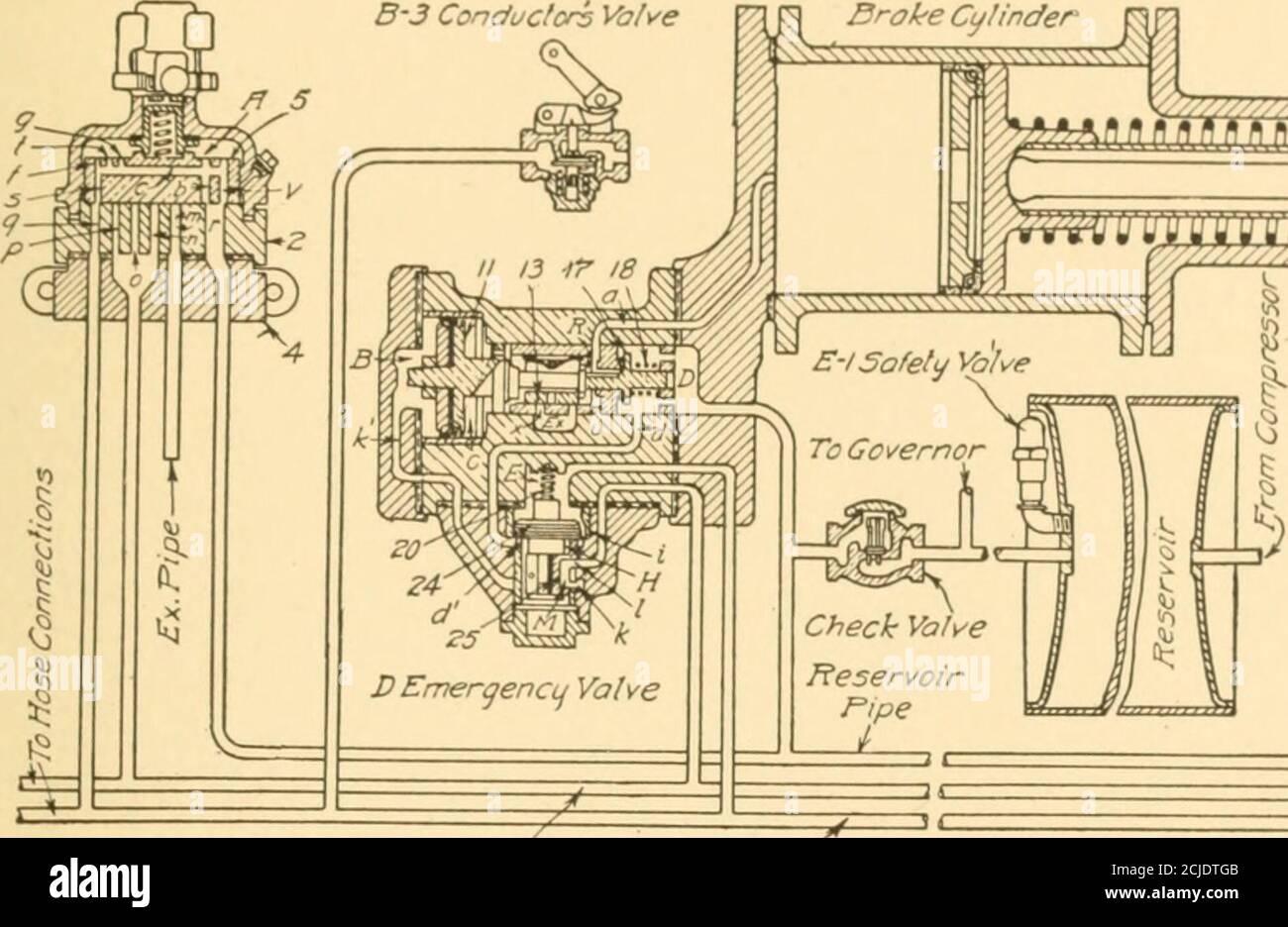
Air Brakes An Up To Date Treatise On The Westinghouse Air Brake As Designed For Passenger And Freight Service And For Electric Cars Uons Slraighl Fiir Application Andrelsas Pipe Emergencu Pipe Tofio3e

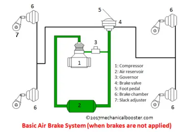
Kelebihan Rem Angin Pada Kendaraan Bus Dan Truk Full Air Brake System Jalur Bus Informasi Seputar Bus Indonesia














0 Response to "40 air brake chamber diagram"
Post a Comment