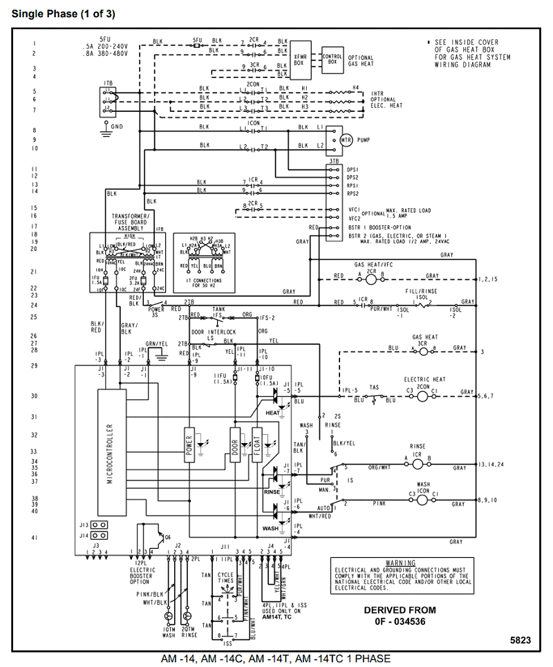
36 phase o matic wiring diagram
Phase O Matic Wiring Diagram – One of the most difficult automotive repair tasks that a mechanic or repair shop can acknowledge is the wiring, or rewiring of a car’s electrical system.The misfortune in fact is that every car is different. in the same way as infuriating to remove, replace or fix the wiring in an automobile, having an accurate and detailed Phase O Matic Wiring Diagram is ... 1. Wire the PHASE-A-MATIC static phase converter to the idler motor as described in Method No. 1, side 1. 2. Size fuses and wires on the single-phase side as appropriate for the motor’s rated amperage. Once running, the idler motor can then power the load motor. Wire the load motor in parallel to the idler motor as per Method 2 diagram No. below.
Nov 21, 2021 · Phase o matic wiring diagram Phase -A- Matic , Inc. is a leading supplier of Phase Converters, Voltage Stabilizers, and Transformers for every industry including: restaurant, clothing, marine & nautical, HVAC refrigeration, hotel, medical, automotive, CNC, metal & woodworking fabrication, agriculture, welding, and a host of other home shop and ...
Phase o matic wiring diagram
Wire the PHASE-A-MATIC static phase converter to the idler motor as described in Method No. 1, side 1. 2. Size fuses and wires on the single-phase side as appropriate for the motor’s rated amperage. Once running, the idler motor can then power the load motor. Wire the load motor in parallel to the idler motor as per Method No. 2 diagram below. Phase O Matic Wiring Diagram – wiring diagram is a simplified within acceptable limits pictorial representation of an electrical circuit.It shows the components of the circuit as simplified shapes, and the power and signal connections along with the devices. Phase O Matic Wiring Diagram. Assortment of phase o matic wiring diagram. A wiring diagram is a simplified standard photographic representation of an electrical circuit. It shows the components of the circuit as simplified shapes, and the power as well as signal links in between the devices. A wiring diagram generally gives info about the…
Phase o matic wiring diagram. Nov 30, 2017 · Phase A Matic Static Converter Wiring Diagram. Static converters on phase a matic inc model pam 200hd 3 4 to 1 2 hp heavy duty converter how does work napcco item r 10 rotary by wiring diagrams quest practical machinist largest manufacturing technology forum the web caution read following carefully before attempting installation 900hd 289 33 8 ... Phase-O-Matic. Work out the size you need: Estimate the size you need by following these three easy steps: 1. List all motors on the system by size and type of use. 2. Add up the horse power rating of each motor to get the total system horse power. 3. Find the model on the chart that correlates to the total system horse power and largest motor ... Phase-A-Matic, Inc. is a leading supplier of Phase Converters, Voltage Stabilizers, and Transformers for every industry including: restaurant, clothing, marine & nautical, HVAC refrigeration, hotel, medical, automotive, CNC, metal & woodworking fabrication, agriculture, welding, and a host of other home shop and commercial applications. Typical Controller Markings Typical Elementary Diagram IEC Typical Controller Markings Typical Elementary Diagram Table 4 Control and Power Connections for Across-the-Line Starters, 600 V or less (From NEMA standard ICS 2-321A.60) 1-Phase 2-Phase, 4-Wire 3-Phase Line Markings L1, L2 L1, L3: Phase 1 L2, L4: Phase 2 L1, L2, L3 Ground, when used
Phase-A-Matic Static Phase Converter Installation regarding 3 Phase Converter Wiring Diagram by admin From the thousands of photographs on the net in relation to 3 phase converter wiring diagram, we all picks the best choices along with best quality exclusively for you all, and now this photographs is usually one among photographs choices in our ideal pictures gallery about 3 Phase Converter ... Phase O Matic Wiring Diagram. Assortment of phase o matic wiring diagram. A wiring diagram is a simplified standard photographic representation of an electrical circuit. It shows the components of the circuit as simplified shapes, and the power as well as signal links in between the devices. A wiring diagram generally gives info about the… Phase O Matic Wiring Diagram – wiring diagram is a simplified within acceptable limits pictorial representation of an electrical circuit.It shows the components of the circuit as simplified shapes, and the power and signal connections along with the devices. Wire the PHASE-A-MATIC static phase converter to the idler motor as described in Method No. 1, side 1. 2. Size fuses and wires on the single-phase side as appropriate for the motor’s rated amperage. Once running, the idler motor can then power the load motor. Wire the load motor in parallel to the idler motor as per Method No. 2 diagram below.

Wiring Diagrams Schematic Wiring Diagram Fpg Schematic Wiring Diagram Fpga Bunn G9 2t Dbc User Manual Page 77 79








0 Response to "36 phase o matic wiring diagram"
Post a Comment