34 8145 20 wiring diagram
Grasslin defrost timer wiring diagram book of paragon 20 dia arcnx paragon defrost timer wiring diagram clock and freezer to 20 paragon defrost timer wiring diagram fresh 20 questions answers with. SPDT X Trippers. Paragon Universal Defrost Timers. Wires directly to V AC, V AC or V AC power sources. without jumpers or switches.
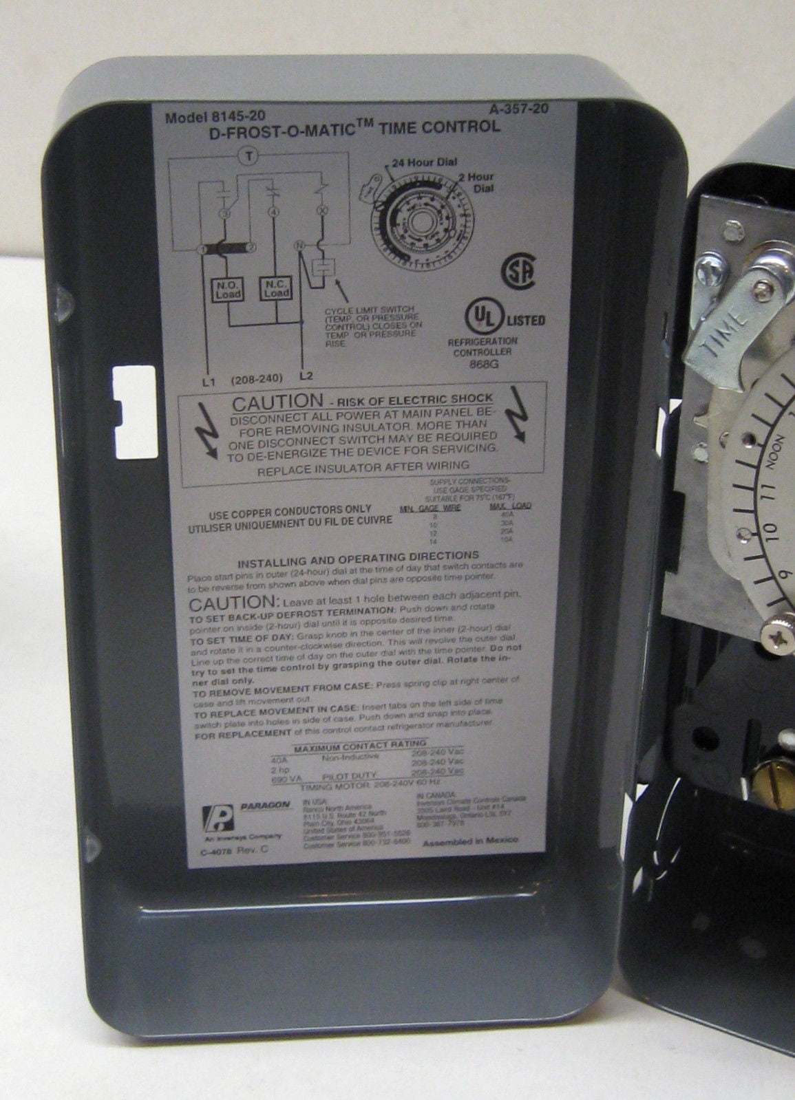
Paragon 8145 20 defrost timer wiring diagram. It reveals the elements of the circuit as simplified forms and also the power and also signal connections between the tools. Collection of paragon defrost timer 8145 20 wiring diagram. 8047 20 208 240 for electric heat defrosting auxiliary contact models 50 hz available open open closed 4 110 min.
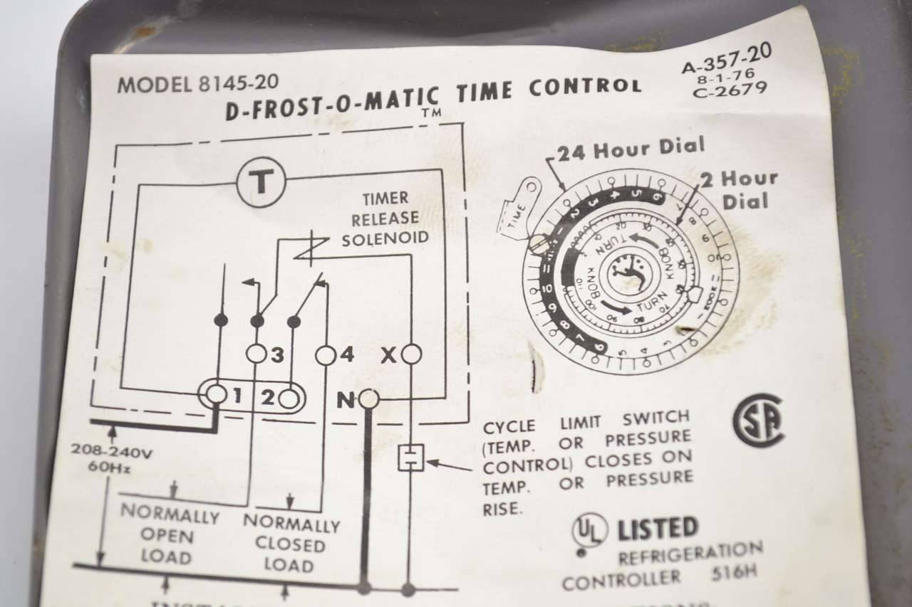
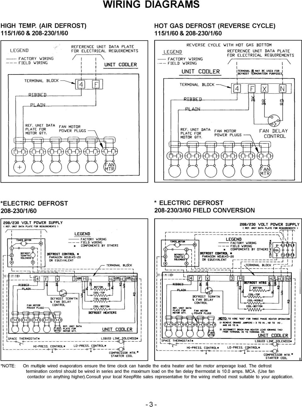
8145 20 Timer Wiring Diagram S and Paragon Available in 6-pack display. Wiring Diagrams Electric Heat Defrosting S & S Series. COMP. HEATER. FAN. L N. The Paragon® defrost and the Tork® electric timers offer versatility and unbeatable Electric Heat,. Hot Gas or Compressor Shutdown. Closed . Open. None. Temp or .
8145 20 wiring diagram
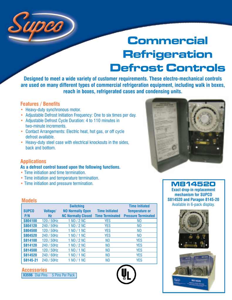
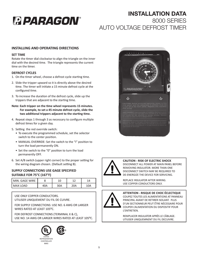
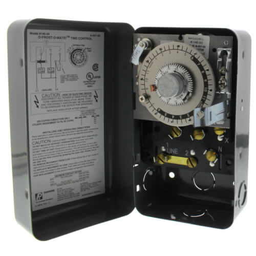
8145-20 8000 Series Defrost Timers The Paragon® 8000 Series Commercial Defrost Controls are designed for commercial freezers and refrigerators to provide automatic defrost capability. They accommodate various types of defrost systems including electric defrost heaters, hot gas, and compressor off cycle. Features and Benefits
What is the difference in part numbers ending in 00 vs. 20? Frequency Voltage Contact state. The UL standard used for temperature regulating (refrigeration)
8145-00 8145-20 8243-20 8245-20 8247-20 AUTO VOLTAGE DEFROST TIMERS 8000 SERIES 2. Wiring Diagrams 8145-AV H (L/L1) N (N/L2) F 3 COMP 1 (L/L1) 2 FAN 5 HEATER 4 (L/L1) X C 8041-00 8041-20 3 (L/L1) X (N/L2) N 3 (L/L1) 4 1 3 (L/L1) DTAV40 3 (L/L1) X (N/L2) 4 2 (L/L1) N 1 3 (L/L1) 8041-00 and 8041-20 Electric Heat Defrosting
8145 20 wiring diagram.
Open. None Initiate 15 minute manual defrost. Mar 18, 2018 - Paragon defrost timer 8145 20 wiring diagram intermatic defrost timers and manuals. Zoom out/reset put photo at full zoom then double click. T101 24 hour timer Have a manual for Paragon Timers? Item # 5X459, Mfr. Grasslin Intermatic G8145-20 Paragon 8145-20 240V Indoor metal (Time -On ...
How to test Paragon 8145-20 defrost timer. Timer dial rotates continuously, and keeps good time. X-3596 Trippers are attached to edge of dial. When.1 page
Description: Paragon Defrost Timer Wiring Diagram Paragon Defrost Timer Wiring regarding 8145 20 Wiring Diagram, image size 577 X 600 px, and to view image details please click the image.. Here is a picture gallery about 8145 20 wiring diagram complete with the description of the image, please find the image you need. We hope this article can help in finding the information you need. 8145 20 ...
8145-20 208-240 None Open Closed Bracket available and 50 Hz. Applications and Wiring Diagrams MECHANICAL DEFROST TIMER 8000 Series. Applications and Wiring Diagrams MECHANICAL DEFROST TIMER 8000 Series Customer Service Telephone 1.800.304.6563 Customer Service Facsimile 1.800.426.0804 HVACCustomerService@robertshaw.com www.robertshaw.com www ...
[PDF] Paragon Timer 8145 20 Wiring Diagram - Free Files. 8145-20ex - Paragon Electric 8145-20ex Timer .... Jul 21, 2018 — Ec4004 Paragon Electric Timer Manual 5,6/10 42reviews. Paragon Electric EC4000 Series Timers Time Controls 24-Hour or 7-Day Interval ....
www.robertshaw.com. Customer Service 1.800.304.6563. REFRIGERATION. D4. Product Drawings. 8047-00 and 8047-20. Electric Heat Defrosting. 8145-AV.3 pages
27.11.2018 27.11.2018 7 Comments on Paragon Defrost Timer 8145 20 Wiring Diagram. Find solutions to your paragon defrost timer 20 wiring diagram question. Get free help, tips & support from top experts on paragon defrost timer Adjustable Defrost Cycle Duration: 4 to minutes in S and Paragon Wiring Diagrams Electric Heat Defrosting S & S Series ...
Models 8145-00, 8145-20, E357-00, D81-8145-ZIEX Wiring Diagram. Wiring using 120V or 240V single phase line with compressor thermostat closed.4 pages
12 Dec 2019 — You need someone to come in and trace the wiring if you cannot figure it out. You said you had the Paragon wiring diagram already, if not the link below can be ...Wiring diagram for paragon defost timer 8145-20 - Fixya1 answer28 Jan 2010Paragon 8145-20 Defrost Timer 8045 wiring diagram2 answers22 Nov 2019I need a three phase wiring diagram for 8145-20 ...1 answer21 Dec 2010Trying to replace a 8045-20 w/ 8145-20 need wiring ...1 answer10 Nov 2010More results from www.fixya.com
8145 20 wiring diagram. 06 jetta 2.5 ignition coils wiring diagram. 2002nissan pathfinder tape stereo wiring diagram. 6.0 powerstroke belt routing. Workhorse wiring diagram motorhome. Stihl hs56c parts diagram. Wiring diagram 88f150 fuel system. Lux performance dvlxs12c wiring diagram.
Collection of paragon defrost timer 8145 20 wiring diagram. A wiring diagram is a simplified traditional photographic depiction of an electrical circuit. It reveals the elements of the circuit as streamlined shapes, and also the power as well as signal links in between the tools.
romex Paragon 8145 20 Wiring Diagram to your "supply" in which this circuit will achieve It is really electricity.. honda cx 400 custom manual, ec4004 paragon electric timer manual, 2010 mitsubishi fuso fe145 manual, mercury outboard 4 5 6 Paragon
Defrost timer product sheet.indd
Collection of paragon defrost timer 8145 20 wiring diagram. A wiring diagram is a streamlined traditional pictorial depiction of an electric circuit. It reveals the elements of the circuit as simplified forms, and also the power and also signal connections between the tools.
Refrigeration
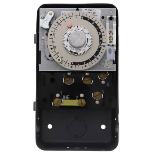
Paragon 8145-20M - 208/240V Defrost Timer - Mechanism Only - Features: Will fit in standard Paragon 8145-20 Housing Case Box. High-amp switch contacts: 40 amps, 2 HP Positive slider bar switch design assures positive electrical contact and wipes the contact surface of contaminates Temperature or pressure terminated models are designed for defrost termination using an external temperature or ...

Paragon timers and manuals:
Paragon 8045 20 Wiring Diagram. Wiring diagram shows both V and V L1 L2 is V L N is V I need wiring diagram for Paragon The - schematron.org Website. The Paragon® defrost and the Tork® electric timers offer versatility and unbeatable quality Electric Heat,. If playback doesn't begin shortly, try restarting your device.
Installation data 8000 series auto voltage defrost timer
S814520 8145-20 6145-20 SUPCO Paragon Precision S804100 8041-00 6041-00 S804120 8041-20 6041-20 S804500 8045-00 6045-00 S804520 8045-20 6045-20 Wiring using differential of SPDT thermostat Wiring using 120V or 240V single phase line compressor thermostat closed during defrost. L 120 N L1 208-240 L2 S814500 & S814520 Wiring Diagrams Hot Gas ...

Supco s8145-20 complete commercial defrost timer (replaces paragon 8145-20)
Applications and wiring diagrams mechanical defrost timer 8000 series. 8145 20 208 240 none open closed bracket available and 50 hz. Here is a picture gallery about 20 wiring diagram complete with the description of the image please find the image you need. A wiring diagram is a simplified traditional photographic depiction of an electrical ...

Paragon 8145-20 defrost timer for commecial refrigeration 220v | ebay
S814520 and Paragon 8145-20 ... Wiring using 120V or 240V single phase line compressor ... Wiring Diagrams Electric Heat Defrosting S8141 & S8145 Series.2 pages
208/240v defrost timer
Through the thousands of photographs on the net about 8145 20 wiring diagram, selects the best series having ideal quality exclusively for you, and this photographs is actually considered one of graphics collections in this ideal photos gallery with regards to 8145 20 Wiring Diagram.Lets hope you will enjoy it. This specific picture (Paragon Defrost Timer 8145 20 Wiring Diagram - Wiring ...
Commercial refrigeration temperature and defrost controls
8145 20 Timer Wiring Diagram Effectively read a cabling diagram, one has to know how the particular components within the method operate. For instance , when a module will be powered up and it sends out a new signal of half the voltage plus the technician will not know this, he'd think he has a problem, as this individual would expect a 12V signal.

Precision multiple controls official website - your source ...
paragon 8145 20 wiring diagram lovely paragon 8145 00 wiring diagram. Architectural wiring diagrams accomplishment the approximate locations and interconnections of receptacles, lighting, and permanent electrical facilities in a building. Interconnecting wire routes may be shown approximately, where particular receptacles or fixtures must be on ...
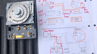
How to test paragon 8145-20 defrost timer.
Assortment of paragon 8145 00 wiring diagram. A wiring diagram is a streamlined traditional pictorial depiction of an electric circuit. It reveals the parts of the circuit as simplified forms, and the power and signal connections in between the gadgets.
Mechanical defrost timer 8000 series
8141-20. SLINE 2. 8143-00. 8143-20. 8145-00. 8145-20. Solid Copper. Contacts. Line Voltage - ... Applications and Wiring Diagrams. WIRING DIAGRAMS FOR 8040 ...4 pages
Auto voltage defrost timers 8000 series
paragon 8145 00 wiring diagram - timer wiring diagrams wiring harness wiring diagram wiring wire rh linxglobal co. File Type: JPG. Source: 107.191.48.167. Assortment of paragon 8145 00 wiring diagram. Click on the image to enlarge, and then save it to your computer by right clicking on the image.
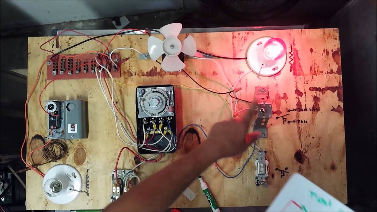
Freezer defrost timer live operation
Paragon 8145-20 - 208/240V Defrost Timer - Designed for commercial freezers and refrigerators, Paragon commercial defrost controls provide automatic defrost capability. They accommodate various types of defrost systems including electric defrost heaters, hot gas and compressor off cycle. Time initiated, temperature or pressure terminated High ...
Mechanical defrost timer 8000 series
Instruction Manuals. To find a publication quickly, you can use the " Filter " above the list to display by Category. You can also use the Search feature for a specific document title or category. You can sort the " Document Title " or the " Category " column using the button to the right of the column title.
Part number: e316008_j
8145-20 8145-21 8243-20 8245-20 8247-20 auto voltage defrost timers 8000 series 2. wiring diagrams 8145-av 8145-av50 8145-av-m 8145-av50m h (l/l1) n (n/l2) f 3 comp 1 (l/l1) 2 fan 5 heater 4 (l/l1) x c 8041-00 8041-20 3 (l/l1) x (n/l2) n 3 (l/l1) 4 1 3 (l/l1) dtav40 3 (l/l1) x (n/l2) 4 2 (l/l1) n 1 3 (l/l1)
Auto voltage defrost timers 8000 series
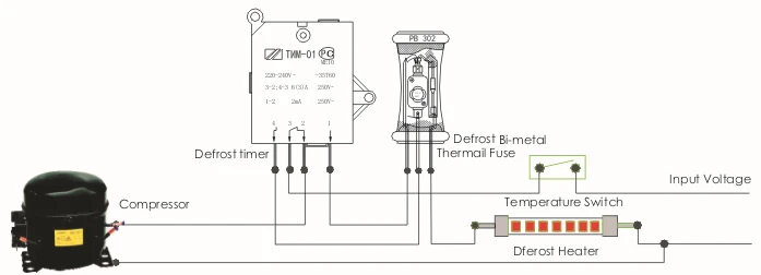
Collection of paragon defrost timer 8145 20 wiring diagram. The defrost timer acts as a clock, that switches the refrigerator from the freezing cycle to the defrost cycle and back. EC series programming manual shows wiring, explains keypad, has steps for setting current time, and shows 24 steps for programming timer. DC could flow not just ...

Paragon timer 8145-20 -8145-20rs
Paragon 8145 20 Wiring Diagram - wiring diagram is a simplified gratifying pictorial representation of an electrical circuit. It shows the components of the circuit as simplified shapes, and the knack and signal connections amongst the devices.
Refrigeration
Paragon 8145-20 d-frost-o-maic time control defrost 208-240v ...

Defrost time & temperature - hvac school
Ton of refrigeration to kw conversion
![How To Get] PDF and Download Paragon 8145 20 Wiring Diagram](https://via.placeholder.com/512.png?text=paragon+8145+20+wiring+diagram)
How to get] pdf and download paragon 8145 20 wiring diagram
Dblt-10 defrost timer for refrigerator freezer - coowor.com
Refrigeration
Refrigeration
Auto voltage defrost timers 8000 series

Intermatic defrost timers and manuals
Robertshaw 8000 series auto voltage defrost timer manual ...
Typical wiring for defrost on a single evaporator freezer
208/240v defrost timer

الصورة النمطية الجبال المناخية لم ألاحظ sankyo defrost timer ...
Hvac-talk: heating, air & refrigeration discussion
Paragon 8145-20 defrost control commercial refrigeration ...
0 Response to "34 8145 20 wiring diagram"
Post a Comment