36 draw the moment diagram for the beam.
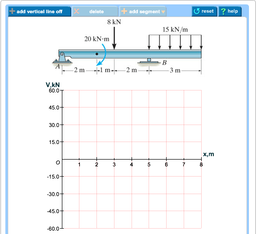
Drawing bending moment diagrams for different beam sections is also a very important part of the strength of material problems. Here, we explain how to draw bending moment diagrams effectively for all problems. Bending diagrams are represented with a straight horizontal line right below the beam. This line represents zero. Transcribed image text: Part A Draw the shear diagram for the beam. Follow the sign convention Click on "add vertical line off" to add discontinuity lines. Then click on "add segment" button to add functions between the lines, Note 1 - Make sure you place only one vertical line at places that require a vertical line.
7:39This is a tutorial to make shear force diagram and bending moment diagram easily for a simply supported ...18 Oct 2016 · Uploaded by Short Notes
Draw the moment diagram for the beam.
9:55This video explains how to draw shear force diagram and bending moment diagram with easy steps for a ...3 Sep 2018 · Uploaded by Eurocoded You will be fully competent in drawing shear force and bending moment diagrams for statically determinate beams and ...23 Jul 2021 · Uploaded by DegreeTutors Positive bending moment diagram drawn BELOW the beam SHEAR FORCE & BENDING MOMENT DIAGRAM + M ... figure, then draw the shear force diagram (SFD) and bending moment diagram (BMD). 5 kN/m 3 m A B EXAMPLE 6 . By taking the moment at A: ΣM A = 0 – R By × 3 + 5 × 3 × 3/2 = 0 R By = 7.5 kN ΣF y = 0 R Ay + By = 5 ×3 R Ay = 15 – 7.5 R Ay kN ΣF x = 0 R Ax = 0 EXAMPLE 6 – …
Draw the moment diagram for the beam.. Draw the complete shearing force and bending moment durams using the techniques shown in Sections 5-3 Determine the magnitude and location of the maximum haute value of the shearing force and bending moment. Ise the free-body diagram approach shown in Sections through 5-5 to determine the internal shearing force ind bending moment at any specified point in a beam. sint 2.86 m. from ximum degan ... 05.03.2021 · Since the function for the bending moment is parabolic, the bending moment diagram is a curve. In addition to the two principal values of bending moment at x = 0 m and at x = 5 m, the moments at other intermediate points should be determined to correctly draw the bending moment diagram. The bending moment diagram of the beam is shown in Figure ... Question: Draw the bending-moment diagram for the beam and the Draw the shear diagram for the beam. This problem has been solved! See the answer ... Any changes made will automatically re-draw the free body diagram any simply supported or cantilever beam. The beam reaction calculator and Bending Moment Calculations will be run once the "Solve" button is hit and will automatically generate the Shear and Bending Moment Diagrams. You can also click the individual elements of this LVL beam calculator to edit the model. Beam Reaction Calculator ...
BEAM DIAGRAMS AND FORMULAS Table 3-23 (continued) Shears, Moments and Deflections 13. BEAM FIXED AT ONE END, SUPPORTED AT OTHER-CONCENTRATED LOAD AT CENTER and Bending Moment Diagrams for Plane Frames Previous definitions developed for shear forces and bending moments are valid for both beam and frame structures. However, application of these definitions, developed for a horizontal beam, to a frame structure will require some adjustments. 12:23Draw the shear and moment diagrams for the beam. 824 views824 views. Feb 25, 2021. 7. 1. Share. Save. 7 ...25 Feb 2021 · Uploaded by BENAM ACADEMY There are also examples and random beam generators which will allow you to experiment on how different loads affect beam analysis and the shear force and bending moment of a beam. Bending Moment Diagram is powered by the team at SkyCiv Engineering - who offer Student and Professional packages that give users access to a variety of Structural Engineering Software to get the job done.
Shear and Moment Diagrams. The shear and moment diagrams shown in Fig. 6–4 c are obtained by plotting Eqs. 1 and 2 . The point of zero shear can be found from Eq. 1 : NOTE: From the moment diagram, this value of x represents the point on the beam where the maximum moment occurs, since by. V = dM/dx = 0 V = dM /dx = 0 . Transcribed image text: Part B Draw the moment diagram for the beam. Follow the sign convention Click on "add vertical line off" to add discontinuity lines. Then click on "add segment" button to add functions between the lines. Note 1 - Draw a vertical line to denote local maximum or minimum. section of a beam : draw a free-body diagram that expose these forces and then compute the forces using equilibrium equations. The goal of the beam analysis -determine the shear force V and the bending moment M at every cross section of the beam. To derive the expressions for V and M in terms of the distance x measured along the beam. By plotting these expressions to scale, obtain the shear ... For the beam and loading shown, (a) draw the shear and bending-moment diagrams, (b) determine the equations of the shear and bending-moment curves. SOLUTION Reactions: 0: 0 B 22 LwL MALwL A 0: 0 A 22 LwL MBLwL B Free body diagram for determining reactions: …
Solved Draw The Shear Diagram For The Beam Draw The Moment Chegg Com
Shear and Moment Diagrams Calculate and draw the shear force and bending moment equations for the given structure. 11 Sketching the Deflected Shape of a Beam or Frame Qualitative Deflected Shape (elastic curve) ≡ a rough (usually exaggerated) sketch of the neutral surface of the structure in the deformed position under the action
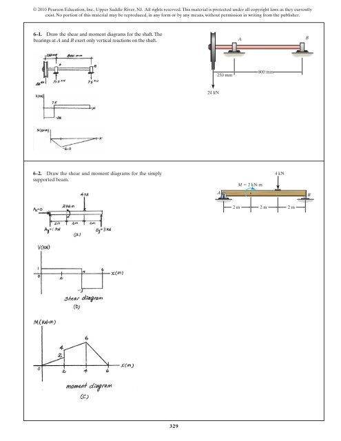
329 6 1 Draw The Shear And Moment Diagrams For Aerostudents
xThe bending moment diagram is obtained by proceeding continuously along the length of beam from the left hand end and summing up the areas of shear force diagrams using proper sign convention. xThe process of obtaining the moment diagram from the shear force diagram by summation is exactly the same as that for drawing shear force diagram from load diagram. xThe bending moment curve is ...

Draw Shear And Bending Diagram For The Beam Given In The Image Study Com
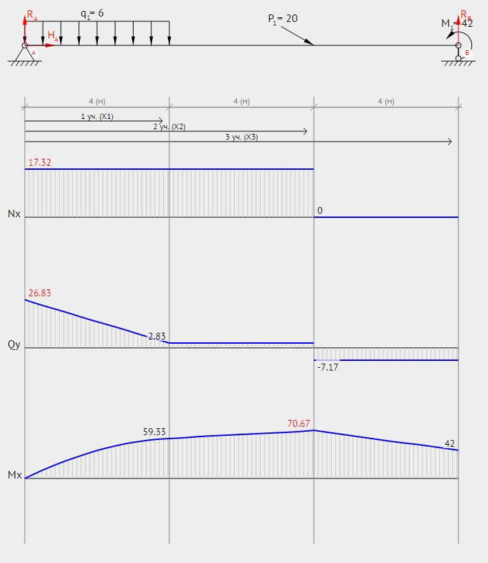
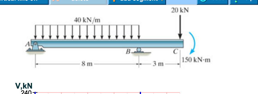
Shear and Moment Functions. Since there is a discontinuity of distributed load and also a concentrated load at the beam’s center, two regions of x must be considered in order to describe the shear and moment functions for the entire beam. M = ( − 2. 5 x 2 2 + 1 5. 7 5 x 2 + 9 2. 5) k N ⋅ m.

Liudesys Ziurėk Nebijok How To Draw Shear Style Nomansworldfestival Com
*7—56. Draw the shear and moment diagrams for the cantilevered beam. 300 1b - diagram of the beam's left through an arbitrary shown in fig. b will be to write the and mcnnent quations. The inœnsity the triangldar útributed load at of sectioning is — = 3333r Referring Fig. b , o V = {-300- 1b — +3001-0 The shear and diagrams shown in ...
Solved Draw The Shear Diagram For The Beam Draw The Moment Chegg Com
Positive bending moment diagram drawn BELOW the beam SHEAR FORCE & BENDING MOMENT DIAGRAM + M ... figure, then draw the shear force diagram (SFD) and bending moment diagram (BMD). 5 kN/m 3 m A B EXAMPLE 6 . By taking the moment at A: ΣM A = 0 – R By × 3 + 5 × 3 × 3/2 = 0 R By = 7.5 kN ΣF y = 0 R Ay + By = 5 ×3 R Ay = 15 – 7.5 R Ay kN ΣF x = 0 R Ax = 0 EXAMPLE 6 – …

How To Calculate And Draw Shear And Bending Moment Diagrams 13 Steps Instructables
You will be fully competent in drawing shear force and bending moment diagrams for statically determinate beams and ...23 Jul 2021 · Uploaded by DegreeTutors
1
9:55This video explains how to draw shear force diagram and bending moment diagram with easy steps for a ...3 Sep 2018 · Uploaded by Eurocoded
2
Chapter 4 Internal Forces In Beams And Frames In Structural Analysis On Manifold Tupress
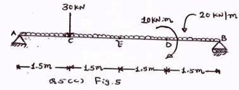
Draw Shear Force And Bending Moment Diagram For The Beam As Nbsp Shown In Figure 5 Nbsp

Shear And Bending Moment Diagrams Of Beam Bending Moment Shear Force Beams

Shear Force And Bending Moment Diagram For Overhanging Beam Mechanical Engineering Concepts And Principles

Draw The Shear Force Diagram And Bending Moment Diagram For The Beam Loaded As Shown In Fig
Bending Shear And Moment Diagram Graphical Method To Construct Shear Ppt Download
Bending Shear And Moment Diagram Graphical Method To Construct Shear Ppt Download
Answered Draw The Shear And Moment Diagrams For Bartleby
Calculations For Shear Force And Bending Moment Diagram For Overhanging Beam
Solved 1 Draw Shear Force And Bending Moment Diagrams For The Beams Subjected To The Loadings Shown Below 2 A Calculate The Shear Forces And Be Course Hero
Shear Diagram Beam With 3 Supports Physics Forums

Shear And Moment Diagram Wikipedia
Solved Draw The Shear Force Bending Moment Diagrams Of The Beam Shown In The Figure Below Taking Into Account The Given Loading Make Detailed Cal Course Hero

05 2 1 Shear And Moment Diagrams Graphical Method Example Youtube
4 5 Practice Problems Learn About Structures

Shear And Moment Diagram Wikipedia
Solution To Problem 403 Shear And Moment Diagrams Strength Of Materials Review At Mathalino
The Ultimate Guide To Shear And Moment Diagrams Degreetutors Com

How To Draw Shear Force Bending Moment Diagram Cantilever Beam Part 3 Gate 2017 Examination Youtube

Drawing Shear Force Bending Moment Diagram File Exchange Pick Of The Week Matlab Simulink
Shear Force And Bending Moment Diagrams Graphical Method Slide Share
Determining The Shear Force And Bending Moment Equations Of Simply Supported Beam

Draw The Shear Force And Bending Moment Diagrams For The Beam Shown In The Figure Below Study Com
Shear And Moment Diagrams Strength Of Materials Review At Mathalino

Draw Shear Force And Bending Moment Diagram For Cantilever Beam Bending Moment Shear Force Mathematical Expression
How To Draw Shear Force And Bending Moment Diagrams Strength Of Materials Quora
Chapter 4 Internal Forces In Beams And Frames In Structural Analysis On Manifold Tupress
Solved Draw The Shear Diagram For The Beam Draw The Moment Chegg Com
0 Response to "36 draw the moment diagram for the beam."
Post a Comment