35 well pressure tank diagram
A pressure tank is an integral part of maintaining your well. Pressurized well tanks extend the lifespan of your well pump by preventing rapid on/off cycling of the pump and maintaining water pressure throughout your home. A properly sized pressure tank ensures your household water needs are met and your pump is protected against short-cycling. Join John Woodard, our Master Water Specialist ... between well and 1" pressure pipe that will rest on the well seal to support the pipes and ejector or jet in ... Leak in the pressure tank 2. Defective air volume control 3. Leak on discharge side of system 4. Leak on suction side of system ... diagram. Provide adequate ventilation or move pump.
This well pressure tank installation video shows the steps you'll need for this replacement. Be sure to follow the proper requirements listed below and in th...
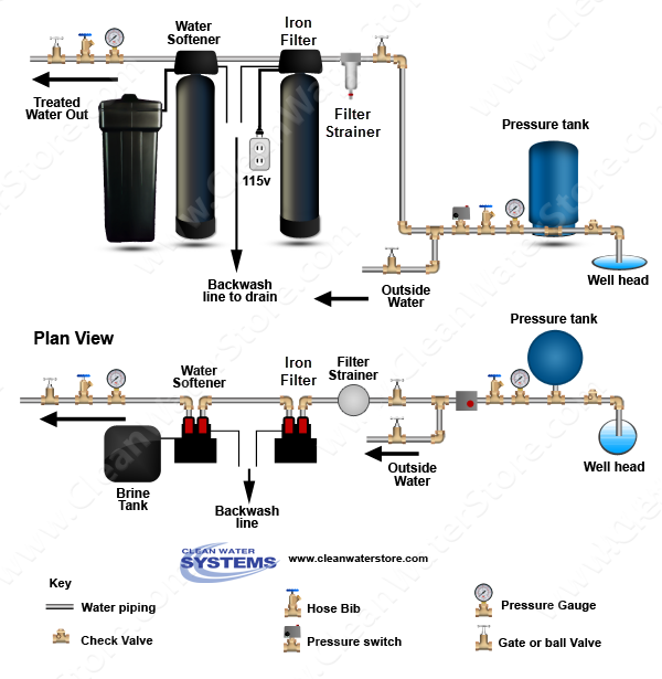
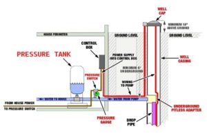
Well pressure tank diagram
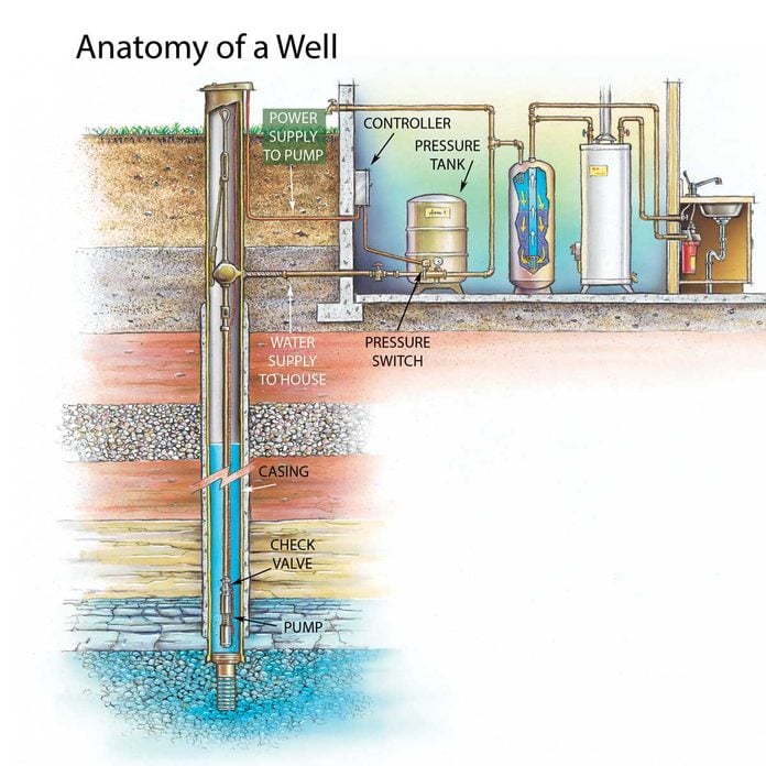
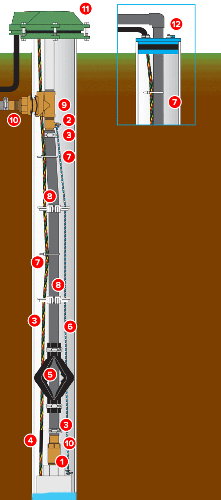
Well Pump & Pressure Tank Diagram. PRESSURE. TANK ... A safety line from the top of the well to the pump. 4. Pitless Adapter. Provides a watertight sanitary ...1 page 32 lbs. Normal Installation. NO TANK Installation. NO TANK Slab-Installation. NO TANK Well Installation. Designed to fit into a 4", 5", or 6" well or larger. The NO TANK is precharged and tested with helium to insure no leakage. Replaces standard pressure tanks where space is a problem. Elimates location and freezing problems for homes built on ... A well water system requires an open source of water coming from the water main, proper pressure readings in the control system, and an adequate amount of air in the well's pressure tank. To diagnose problems with pressure, you'll need to...
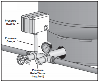
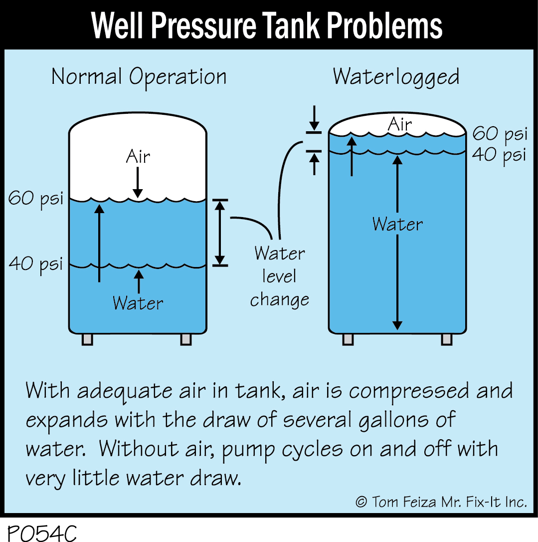
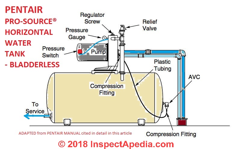
Well pressure tank diagram. Click to View Larger Image Well Water System, Water Systems, Well Water Pressure Tank. Need to Know - Well Drilling, Water Treatment Systems - Lowcountry, ... Water Well Pressure Tanks. As water is pumped from the well into the pressure tank, it compresses the air in the tank until it reaches a preset level, typically the 40 to 60 pounds per square inch (psi). When someone turns on a faucet, air pressure in the tank forces water throughout the plumbing until the pressure drops to the preset trigger ... Well head & pressure tank pictures / illustrations Use this hand diagram and photo to plan your own design of above ground or wellhead equipment installation Jonathan Knapp Well Pump & Water Pump Controls: This article describes and identifies the switches, controls, and safety devices used on water tanks and water pumps such as the pump pressure control switch, pump motor relays, water tank relief valve, water tank pressure gauge, water tank air volume control, and water tank air valve.
The pump tank has been shipped with a factory precharge as indicated on Table 1. If your pump start-up pressure is different from the factory precharge, adjust the tank pressure with the tank empty to your pump start-up pressure. This can be accomplished by simply bleeding air from valve in the top of the tank with an accurate pressure gauge. Well Pump Pressure Switch Wiring Diagram Collection. Collection of well pump pressure switch wiring diagram. A wiring diagram is a simplified traditional photographic representation of an electric circuit. It reveals the parts of the circuit as simplified forms, and the power as well as signal connections between the tools. A wiring diagram usually gives info concerning the… 6. Well Seal. Provides a positive seal inside the casing in above-ground installations. 7. Check Valve. Installed near the tank inlet to hold water in the tank during pump installation when the pump is idle. 8. Tank Tee. Connects water line from the pump to pressure tank and service line from tank to house. pressures (75 psig or more). This will protect the well tank and other system components should the pressure switch malfunction and fail to shut the pump off. The relief valve should be installed at the connection of the well tank to the system piping and have a discharge equal to the pump's capacity at 75 psig. At least once every 3 years
The pressure in the tank is what moves the water through the household plumbing system. When the pressure reaches a preset level, which can be anywhere from 40 to 60 psi, a switch stops the pump. Tank Tee Packages in Brass or Stainless Steel are designed to connect your pressure tank to your water line. Each package comes with a tank tee, full port ball valve, check valve, hose bib, 100 PSI pressure relief valve, male adapter (to connect to your incoming well line), pressure gauge, and a Square-D pressure switch with a choice of pressure settings. Diagrams --Typical Pump Installations. The information provided here is for educational purposes only. Technically qualified personnel should install pumps and motors. We recommend that a licensed contractor install all new systems and replace existing pumps and motors. Failure to install in compliance with local and national codes and ... The tank pressure must be set 2 PSI lower than the pump cut-on pressure. Check tank pressure with a standard air gauge at the top of the tank as needed. ˆ$˘(2 ())'&(Where space is a critical factor, the in-line tank may be used or the <ˆ ˛ ˘ ˘ ˇ Various installations are shown. Also, to increase tank capacity up
DIAPHRAGM PRESSURE TANK DRAWDOWN CHARTS AIR-E-TAINER® PRE-PRESSURIZED WELL SYSTEM TANKS Part No. Model No. Total Tank Volume Gallons Equiv Standard Pressure Tank*** Drawdown-Gallons by PSI Settings Approx. Size In. Dia x Ht Ship Wt. Lbs. NPT Size/ MTL Factory Precharge PSIG Max Working Pressure (PSI) Max Working 20/40 30/50 40/60 Temp
The pump tank has been shipped with a factory precharge as indicated on the tank label. If your pump start-up pressure is different from the factory precharge, adjust the tank pressure with the empty tank to your pump start-up pressure. This can be accomplished by simply bleeding air from valve in the top of the tank with an accurate pressure ...
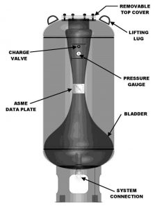
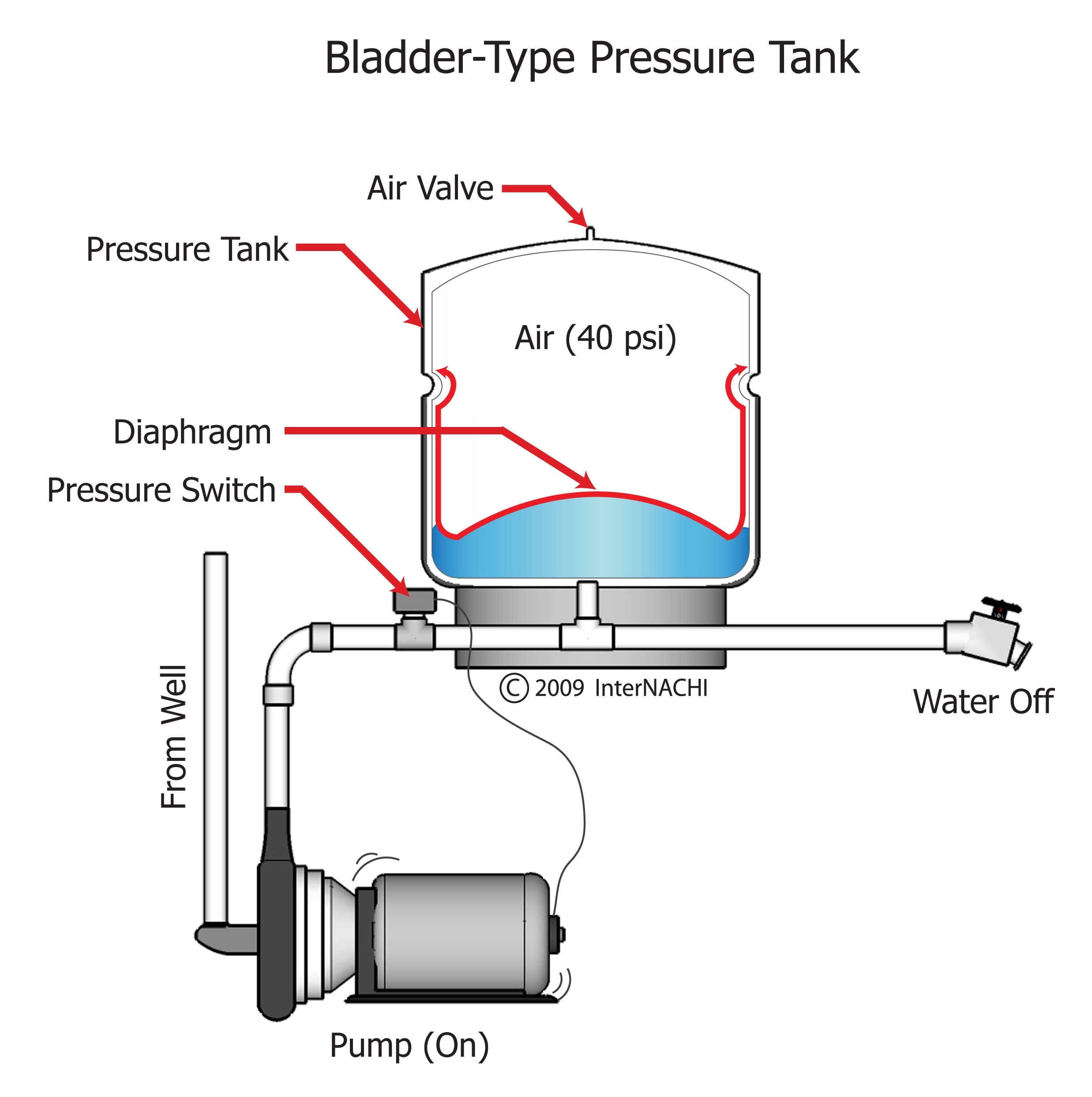
Pressure Pressure Switch How a Well Tank Works 1. As the pump fills the tank with water, the air above the diaphragm is compressed. This increases the pressure in the tank and causes the pressure switch to turn off the pump. 2. When water is used, it is drawn from the tank and the pressure inside the tank decreases. The reduced pressure starts the
The pump then refills the pressure tank. A check valve (a one-way valve) keeps the pressure in your pressure tank from flowing back down the well. The combination of the pressure tank, pressure switch, check valve and pump is what allows water to flow through your home. Pressure tanks, which also act as mini storage tanks for your home, are ...
• Submersible pump sub pac which includes pressure switch, pressure gauge, service tee, relief valve, sub cable and built-in check valve • Pressure tank • Torque arrestor • Well seal or pitless adaptor • 1" discharge piping HOTLINE 888.956.0000 www.RedLionProducts.com Precharged Tank Service Valve To Service Pressure Switch Priming
The pump tank has been shipped with a factory precharge as indicated on the tank label. If your pump start-up pressure is different from the factory precharge, adjust the tank pressure with the empty tank to your pump start-up pressure. This can be accomplished by simply bleeding air from valve in the top of the tank with an accurate pressure ...
Is It Possible To Fill A Water Storage Tank And Pressure Tank From One Well Pump Terry Love Plumbing Advice Remodel Diy Professional Forum
Pentair WellMate Tank Accessories and Replacement Parts. Our accessories include everything you need to complete your WellMate installation. For your convenience accessories are grouped according to product type - captive air tank, non-captive air tank and quick-connect systems.
Well Diagram. The quality water system products described here and illustrated are some of the Baker Water Systems products used in a typical well system. This list and the illustration are not intended as an installation guide. ... Connects water line from pump to pressure tank and service line from tank to house. Taps are provided to accept ...
WELL SEAL (Section K) Used in above-ground installations to provide a positive seal inside casing. CHECK VALVE (Section G) On pump installations, a Check Valve installed near the tank inlet holds water in the tank when the pump is idle. TANK TEE (Section O) Connects water line from pump to pressure tank and service line from tank to house.
Watch the pressure switch until your submersible well pump kicks on. If the pump kicks on at 30 psi, your tank is likely set at 30/50. If your pump turns on at 40, your pressure switch is probably set to 40/60. To make sure, turn off the faucet and wait until the well pump turns off.
Basic overview of a well water system and how it works with a softener and conditioning filter showing all the well componentsGood for new homeowner's who wa...
Water Pressure Tank Installation Diagram. The image below shows the typical installation diagram of a well pressure tank, as well as other components of a well system. Image: Lakeland Water Pump How a Bladder Pressure Tank Works. A bladder pressure tank is a steel tank with a bladder inside which looks like a balloon.
A well water system requires an open source of water coming from the water main, proper pressure readings in the control system, and an adequate amount of air in the well's pressure tank. To diagnose problems with pressure, you'll need to...
32 lbs. Normal Installation. NO TANK Installation. NO TANK Slab-Installation. NO TANK Well Installation. Designed to fit into a 4", 5", or 6" well or larger. The NO TANK is precharged and tested with helium to insure no leakage. Replaces standard pressure tanks where space is a problem. Elimates location and freezing problems for homes built on ...
Well Pump & Pressure Tank Diagram. PRESSURE. TANK ... A safety line from the top of the well to the pump. 4. Pitless Adapter. Provides a watertight sanitary ...1 page
Air Injection Dual Tanks Sequencing Question Terry Love Plumbing Advice Remodel Diy Professional Forum
How To Determine Your Well Pump Flow Rate On Wells With Pressure Tanks Residential Well Water Treatment Iron Filters Acid Neutralizers Chlorinators










0 Response to "35 well pressure tank diagram"
Post a Comment