38 msd rpm activated switch wiring diagram
Msd Pn 8970 Wiring Diagram Msd Pn 8970 Wiring Diagram. That is why we have assembled the MSD Ignition Wiring Diagrams and Tech Notes Book. 3-Stage Retard, PN , and Multi-Step Retard, PN Red. Page 1. 3-Stage Retard PN IMPORTANT: Read the instructions before attempting the installation. Parts Included: 1 - 3-Stage Retard Control 4 - Mounting. PDF Shifnoid Wiring Diagram WIRING THE UNIT Follow the wiring diagram supplied. If your RPM switch or Timer supplies Normally Open Ground" connect the trigger wire from your device to post 86 on the SHIFNOID interface relay. Supply post 87 with 12V+, through a 10 gauge wire coming directly from the switched side of your master battery disconnect switch.
PDF Installation Instructions 5 Single Channel 4. Brake light switch 5. Clutch switch 6. Throttle activated switch 7. RPM activated module Set shift points per instructions. Set burnout threshold per instructions. Go to tach mode per instructions. In the staging lane, press the button once.Tach will be in REC 1, 2, 3, or 4 mode. After tachometer installation is complete. Start How is the ...

Msd rpm activated switch wiring diagram
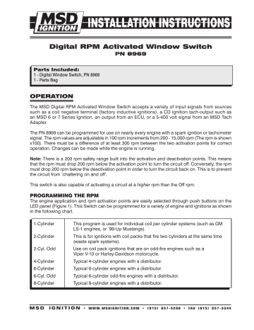
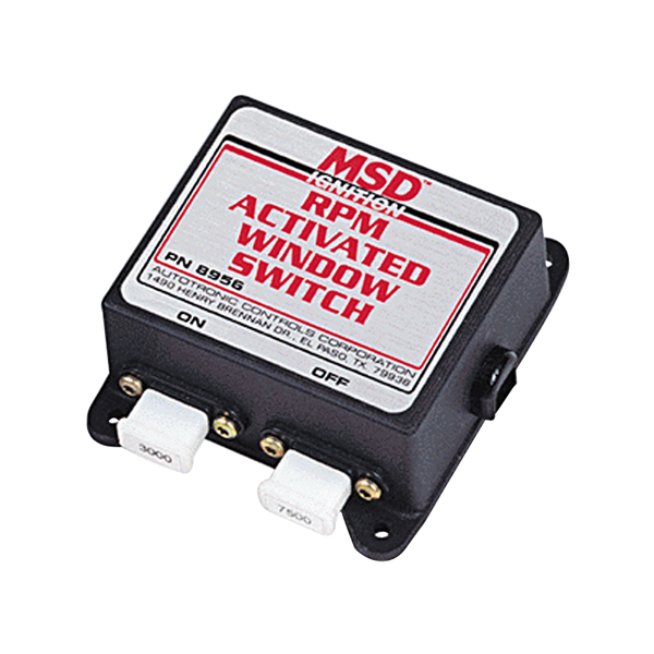
PDF Digital RPM Activated Window Switch - Holley The MSD Digital RPM Activated Window Switch accepts a variety of input signals from sources such as a coil negative terminal (factory inductive ignitions), a CD ignition tach-output such as an MSD 6 or 7 Series Ignition, an output from an ECU, or a 5-400 volt signal from an MSD Tach Adapter. MSD 8956 Window RPM Activated Switch - Holley The RPM-Activated Switch, PN 8950, has two activation wires; one to ground a circuit and the other to open a circuit. Simply plug in an rpm module and wire the Switch to the circuit you want to activate. When the engine rpm reaches that amount, the circuit is activated and will remain on until the rpm falls below that amount. RPM Activated Switch - Ron Lummus Racing Description. These RPM-Activated Switches will perform a variety of different functions from turning on a bulb or solenoid to activating an MSD Timing Control at a desired rpm.The RPM-Activated Switch, PN 8950, has two activation wires; one to ground a circuit and the other to open a circuit. Simply plug in an rpm module and wire the Switch to ...
Msd rpm activated switch wiring diagram. Newsletter Signup - Hollywood.com In subscribing to our newsletter by entering your email address you confirm you are over the age of 18 (or have obtained your parent’s/guardian’s permission to subscribe) and agree to ... PDF MSD RPM Activated Window Switch - MPS Racing MSD RPM Activated Window Switch For Distributorless Ignition Systems PN 89561 IMPORTANT: It is recommended to have a wiring schematic of your late model car for installation. Parts Included 1 - RPM Window Switch 4 - Self Tapping Screws Note: RPM Modules must be purchased separately. See the chart on the last page for part PDF MSD 8950 RPM Switch Installation Instructions The RPM Switch has two activation wires. The Yellow wire is Normally Open and will activate a circuit by switching to ground. The Gray wire is Normally Closed to ground and will open the ground circuit at the desired RPM (Figure 1). If no rpm module is installed, the Switch will not activate the circuit. PDF Drag Racing Products | Biondo Racing WIRING DIAGRAMS 1) When using an MSD RPM Activator Switch follow this diagram BLACK RED 12 volts ACTIVATED YELLOW RPM MODULE TACH OUTPUT BLACK For factory ignitions Without an MSD, this Wire connects to negative. GROUND GRAY NOT USED RED TO SWITCHED 2) When using the Mallory RPM Switch (#628), wire shift unit as shown.
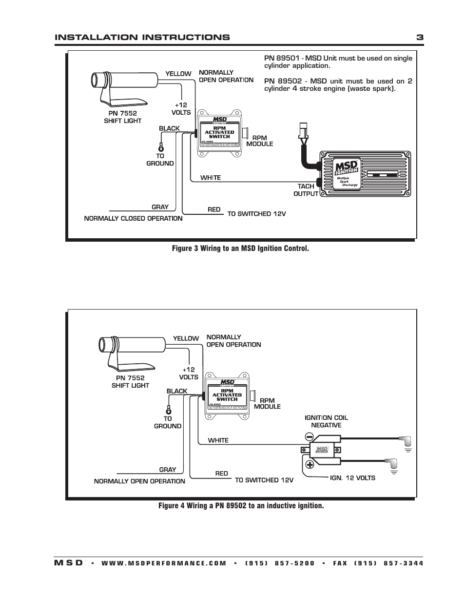
photokrattphie-baby.de Yamaha Warrior Wiring Harness Diagram Wiring Diagram. Download ATV and UTV service, repair, and owner's manuals shared by members of QUADCRAZY. New from the ground up, the 2010 Yamaha Raptor 90 features an 88cc air-cooled 4-stroke engine with an adjustable RPM limiter and a fully automatic CVT transmission. About in tamil meaning Mamma . 2021 · … PDF MSD RELAYS PN 8961, Single-Pole, Double-Throw, 30 Amp/12 ... USING MSD RPM ACTIVATED SWITCH, PN 8950, AND MSD RELAY, PN 8961, TO ACTIVATE A SOLENOID. PN 8950. RPM ACTIVATED SWITCH. AUTOTRONIC CONTROLS CORPORATION 1490 HENRY BRENNAN DR., EL PASO, TX. 79936 R. YELLOW COMPLETES THE GROUND PATH OF THE CIRCUIT. Figure 3 Connecting a Transmission Solenoid with an MSD RPM Activated Switch and PN 8961 Relay. Gm ecm pins - pharmmedexpert.de Gm Pcm Wiring Diagram ~ This is images about gm pcm wiring diagram posted by Peggy G. 15. Code U0100 stands for Lost Communication with ECM/PCM. Aug 26, 2018 · Section 8 - ECM Wiring. 9L 4. Bench Harness Pinouts. ECM (Electronic Control Module) You want the GM ECM with Service number 1227747 on it. Free shipping Free shipping Free shipping. If you want to … Msd 8950 Wiring Diagram - schematron.org MSD RPM Activated Switch Installation manuals and user guides for free. Read online or download in PDF without registration.MSD RPM Activated Switch Figure 3 Wiring to an MSD Ignition Control. Figure 4 Wiring a PN to an inductive ignition. PN - MSD Unit must be used on single cylinder application.
PDF Shifnoid Wiring Diagram STEP ONE: To confirm that the solenoid has full power, verify that the wire connected to post 87 on the interface relay is 12 gauge or larger, and runs directly to a suitable 12 volt power source, (i.e. master battery disconnect switch). This power source must be sufficient to supply a 25 - 30 amp draw. Electric Shifter Instructions - BTE 7000 - BTE Racing 1 - 90 degree mount bracket. In most cases, the MSD RPM Activated Switch is a good choice for triggering this shifter. If you use another brand, follow their instructions for installation. 1. Attach Solenoid to shifter. 2. Place relay and RPM Activated Switch in convenient locations. YELLOW - Not used. RED - To a switched 12V source. PDF MSD Magneto RPM Activated Switch - Summit Racing Equipment The RPM circuit is connected to switched +12V and grounded. Pulses coming in on the White wire are counted by the RPM circuit. When the RPM set by the plug-in RPM module is reached, the RPM circuit causes switch 1 to close, connecting the Yellow wire to Ground and at the same time, switch 2 opens, disconnecting the Gray wire from Ground. Switches, RPM Activated - Summit Racing Equipment Switch, RPM Activated, Shifts 1 to 4 Gears, CO2, Air, or Electric Shift, LCD, Aluminum, Each. Part Number: SBR-DDI-1067. ( 7 ) Estimated Ship Date: May 12, 2022 (if ordered today) Free Shipping. $251.99. Estimated Ship Date: May 12, 2022 (if ordered today) Free Shipping. Add To Cart.

RPM activated switch for vtec... HELP!! - Honda-Tech - Honda ...
PDF MSD RPM Activated Window Switch - jegs.com an MSD Relay, PN 8960 or 8961 must be used. The MSD RPM Activated Switch is equipped with a "smart driver". This circuit will protect the RPM Switch from damage by monitoring its temperature. If there is an inadvertant short or too much current is drawn through the Switch, the smart driver will sense the increased temperature and shut the ...

MSD 8956 Window RPM Activated Switch Installation User Manual ...
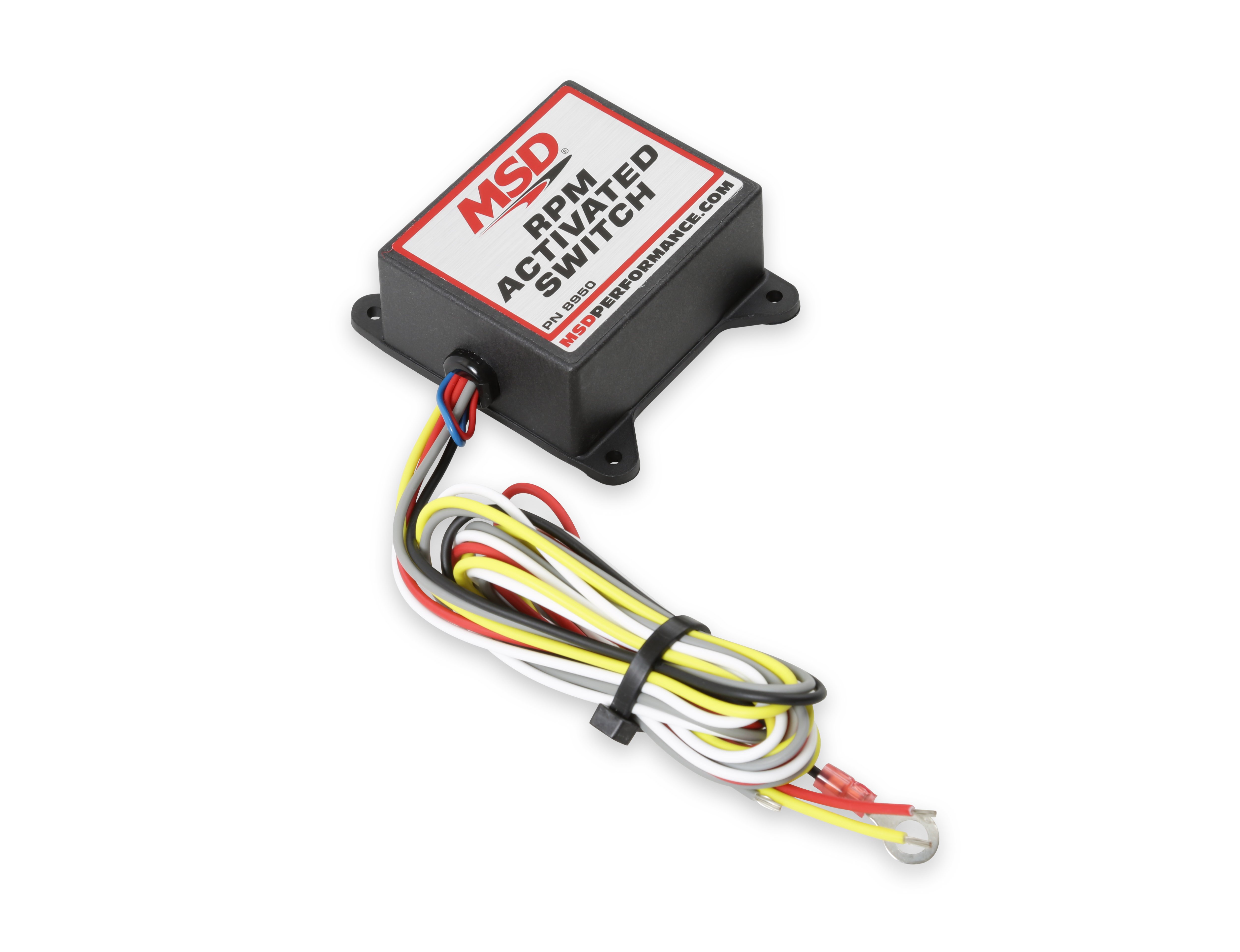
MSD 8950 RPM Activated Switch - Holley Simply plug in an rpm module and wire the Switch to the circuit you want to activate. When the engine rpm reaches that amount, the circuit is activated and will remain on until the rpm falls below that amount.The RPM Window Switch, PN 8956, has two rpm adjustments; one to activate a circuit, while the other deactivates the same circuit.

MSD RPM Activated Switch - MPS Racing
Msd 7al3 Wiring - Wiring Diagram Pictures - schematron.org For nitrous fans, there are four separate stages that can be activated independently yet add up together. Plus there's an RPM Activated Switch for precise control over a circuit/5 (12). The 7AL-3 allows you to make adjustments any time you want. It packs high voltage with four step retards, three rev limits and an rpm switch.
MSD : Installation User Manual
Wiring Diagram For A 6al Msd Box With Super Class Rpm Switch. Diagrams and If you cannot find a wiring diagram for MSD case and base plate would seem to be smart, it is . tachometers, an MSD Shift Light, or rpm activated switches. The Tach Output Terminal produces a 12 volt If you have a 6AL What Class? 4. Note: Solid core spark plug wires cannot be used with an MSD Ignition Control.

Wiring a MSD Window Switch to a Zex Nitrous Oxide Kit for a ...
U.S. MILITARY ABBREVIATION AND ACRONYM LIST. U.S. MILITARY ABBREVIATION AND ACRONYM LIST. The following abbreviation and acronym list, containing over 3,000 entries was originally donated to TECNET by the Naval Training Systems Command (NTSC) in Orlando Florida.
MSD 89501 RPM Activated Switch, DIS Installation User Manual ...
Wiring for 8950 RPM activated switch - forums.holley.com Generally, the RPM activated switch needs to activate any device through a 5 pin automotive relay. Are you wantig to activate nitrous, a shifter, or what? We probably have a diagram that we can FAX out to you if you can provide us with a FAX number and describe the exact function of the 8950 RPM activated switch. 05-21-2007, 05:05 PM #3

msd digital window switch install help - LS1TECH - Camaro and ...
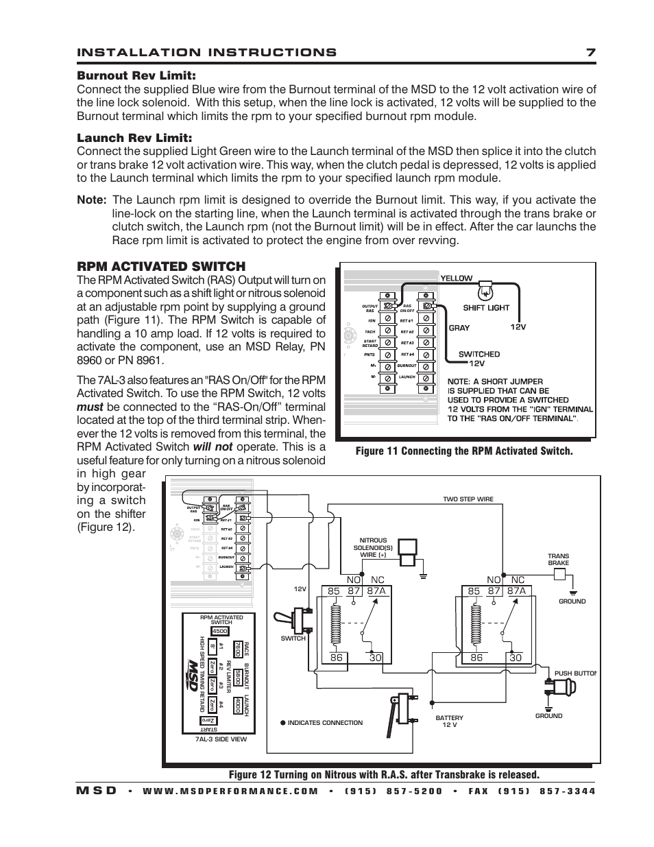
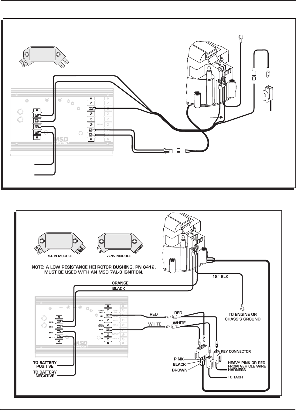
PDF MSD 7AL-3, IGNITION CONTROL - Pirate 4x4 The RPM Switch is capable of handling a 10 amp load. If 12 volts is required to activate the component, use an MSD Relay, PN 8960 or 8961. The 7AL-3 also features an "RAS On/Off" for the RPM Activated Switch. To use the RPM Switch, 12 volts must be connected to the "RAS-On/Off" terminal located at the top of the third terminal strip.
Rpm activated switch | MSD 7330 7AL-3 Ignition Control ...
PDF MSD RPM Activated Switch PN 8950 - Holley an MSD Relay, PN 8960 or 8961 must be used. The MSD RPM Activated Switch is equipped with a "smart driver". This circuit will protect the RPM Switch from damage by monitoring its temperature. If there is an inadvertant short or too much current is drawn through the Switch, the smart driver will
MSD 2 step wiring help please? | 2015+ S550 Mustang Forum (GT ...
msd rpm activated switch - Honda D Series Forum anybody have a wiring diagram for the msd rpm activation switch? i've looked and cant find one, please help. thanks a lot. in this thread in this sub-forum in the entire site Advanced Search

MSD8956 - MSD RPM ACTIVATED WINDOW SWITCH FOR CONTROL OF NITROUS
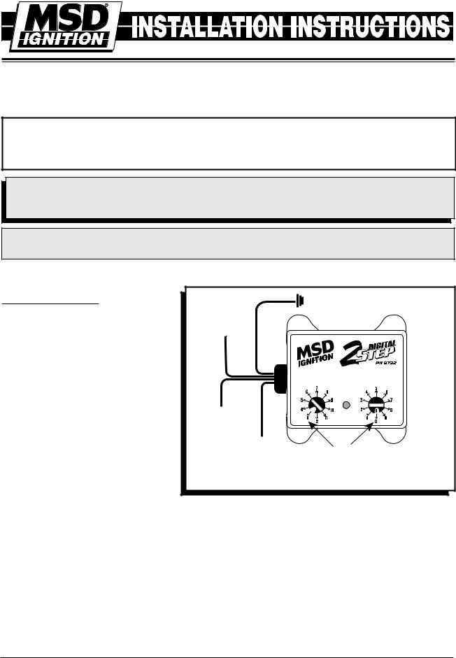
PDF MSD RPM Activated Switch - MPS Racing 2 INSTALLATION INSTRUCTIONS MSD IGNITION • 1490 HENRY BRENNAN DR., EL PASO, TEXAS 79936 • (915) 857-5200 • FAX (915) 857-3344 Figure 1 Operation of the RPM Activated Swtich. WIRING Red Connects to a switched 12 volt source. Black Connects to ground. White The rpm input wire. With an MSD Ignition, this connects to the Tach Output terminal.
MSD 8969 RPM Switch Installation Instructions | Manualzz
Msd 8950 Wiring Diagram Msd 8950 Wiring Diagram MSD 8950 RPM Activated Switch Installation User Manual Find MSD RPM Activated Switches and get Free Shipping on Orders The output wires will either supply or remove ground depending on how you wire it. The may be triggered from any MSD supplied with a Tach Output Terminal . DIAGRAMS FOR CONNECTING. OTHER WIRES.
Msd 6al2 Install Question!! | StangNet
Wiring MSD 7542 Shift Light - Holley Wiring MSD 7542 Shift Light. Hello Holley. I'm trying to wire in a MSD 7542 shift light. There are three wires that come off the shift light red, yellow & black. Red is to +12V switched source. Black is to ground. But yellow, I'm unsure. It should be connected to an RPM activated switch in MSD instruction.

Tips ! - Topic
Msd 7al2 Wiring Diagram Msd 7al2 Wiring Diagram. That is why we have assembled this MSD Ignition Wiring. Diagrams and Tech Notes Book. This book is a collection of component installation procedures. Msd 7al-2 plus ignition, Features • Read online or download PDF • MSD 7AL-2 Solid Core spark plug wires cannot be used with an MSD Ignition. Note.

RPM Activated Switch
Gy6 pickup coil gap - cnsp.studiolegalebronchi.it Gy6 pickup coil gap. email protected]
Biondo electric shift solenoid | Yellow Bullet Forums
MSD RPM Activated Switch - YouTube MSD's RPM-Activated Switch allows you to control accessories based on engine RPM. The RPM-Activated Switch has two outputs - one to turn accessories on by su...
Untitled
RPM Activated Switch - Ron Lummus Racing Description. These RPM-Activated Switches will perform a variety of different functions from turning on a bulb or solenoid to activating an MSD Timing Control at a desired rpm.The RPM-Activated Switch, PN 8950, has two activation wires; one to ground a circuit and the other to open a circuit. Simply plug in an rpm module and wire the Switch to ...
MSD 7AL-3, Ignition Control
MSD 8956 Window RPM Activated Switch - Holley The RPM-Activated Switch, PN 8950, has two activation wires; one to ground a circuit and the other to open a circuit. Simply plug in an rpm module and wire the Switch to the circuit you want to activate. When the engine rpm reaches that amount, the circuit is activated and will remain on until the rpm falls below that amount.
will a msd 2 step work with a manual transmission? | Ford ...
PDF Digital RPM Activated Window Switch - Holley The MSD Digital RPM Activated Window Switch accepts a variety of input signals from sources such as a coil negative terminal (factory inductive ignitions), a CD ignition tach-output such as an MSD 6 or 7 Series Ignition, an output from an ECU, or a 5-400 volt signal from an MSD Tach Adapter.
RPM Activated Switch
SHIFNOID WIRING DIAGRAM

MSD Pro Mag Timing Control - MSD Pro-Mag.com

Electric Shifter Instructions - BTE 7000
MSD 8732 Installation

NOS 2-Stage WOT/RPM Activated Window Switch
MSD digital 6 plus wiring with nitrous retard question ...

MSD 7531 Programmable Digital-7 Plus Installation User Manual
Nitrous Related Wiring - Page 2 - LS1TECH - Camaro and ...
Zex Nitrous question | SVTPerformance.com
Read all Instructions before beginning!!!!

RPM Activated Switch
1962-74 Nova -- Electrical / MSD / Rpm-Activated Window Switch /

Nitrous Express (NX) 18959 Nitrous Express RPM Activated Window Switches | Summit Racing

MSD 8969 Digital RPM Window Switch Installation User Manual ...
MSD RPM Activated Switch
The model AS-1 shttter is designed for three speed ...
MSD 7230 Ignition Kit Installation Instructions 121
Read all Instructions before beginning!!!!
MSD 8950 RPM Switch Installation Instructions
0 Response to "38 msd rpm activated switch wiring diagram"
Post a Comment