40 fe cr phase diagram
Download scientific diagram | The Fe-Cr-C ternary phase diagram (a) Liquidus projection and (b) at 870 ° C. from publication: Microstructural evolution with various Ti contents in Fe-based ... English: The different version of File:Diagramme phase Fe Cr.svg.The horizontal axis label has been changed to English, and the blank space has been reduced. According to the description of File:Diagramme phase Fe Cr.svg, this diagram was made based on the source "Phase diagramme iron-chromium as per BAIN and ABORN - Metals handbook, American Society for Metals, 1948, 1194".
Download scientific diagram | The ternary phase diagram of Ni-Fe-Cr with the liquidus temperatures (blue diamonds) and the liquidus minima (brown hexagons) along the three binaries system. The red ...

Fe cr phase diagram
Phase Diagram 1. Chapter-5 PHASE AND PHASE EQUILIBRIUM Prepared By: PALLAV RADIA Asst prof. AITS, RAJKOT. 2. Introduction: One of the most important objective of engineering metallurgy is to determine properties of material. The properties of material is a function of the microstructure which depend on the overall composition and variable such as pressure and temperature. Hence to determine ... the ternary phase diagram with respect to the aus-tenite stabilized region in the low Cr composition has not beenentirely identified evenin the recent st.udy. Thepurpose of this study is to investigate the eq,ui-librium phasediagram of Fe-Cr-Mnsystem at 923 K (650'C), in particular, to examine the extent of a single phase reg_ion in the low Cr ... 1273K-C-Cr-Fe FSstel: 1273K-C-Fe-Mn FSstel: Ag-Al FScopp: Ag-Al FTlite: Ag-Al SGnobl: Ag-Al SGTE 2014: Ag-Al SGTE 2017: Ag-Al SGTE 2020: Ag-Al-Au_500C SGnobl: Ag-Al-Bi_870C SGnobl: Ag-Al-In_650C SGnobl: Ag-Al-Mg_liquidus SGnobl: Ag-Al-Pb_870C SGnobl: Ag-Al-Si_500C SGnobl: Ag-Al-Si_liquidus SGnobl. Ag-Al-Sn_25C SGnobl: Ag-Al-Sn_liquidus SGnobl ...
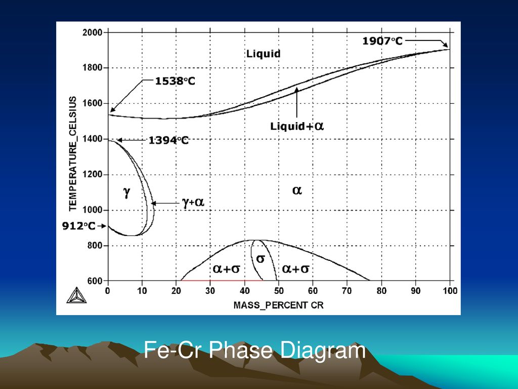
Fe cr phase diagram. Phase diagrams for FE-CR-NI based alloys. Part 1: Phase diagrams for binary and ternary alloys of FE, CR and NI with C and with SI. EU publications. Download Order. Iron -chromium phase diagram Fe-Cr phase diagram shows which phases are to be expected at equilibrium for different combinations of chromium content and temperature. The phase diagram of the Fe-Cr binary system is at Fig 1. The melting point of Fe and Cr is taken at the pressure of 1 atmosphere as 1538 deg C and 1907 deg C respectively. Journal of Phase Equilibria - 76Mir: D. A. Mirzaev, N.M. Mirzaeva, and Kh.M. Ibragimov, "The Fe-Cr-C Phase Diagram in the(Fe γ Cr γ)7C 3 Region,≓Sb. Nauchni. Phase diagram of Fe-Cr-Co permanent magnet system - IEEE Journals & Magazine Phase diagram of Fe-Cr-Co permanent magnet system Abstract: The miscibility gap of the α phase in Fe-Cr-Co permanent magnet alloys is constructed using mechanical hardness and Curie temperature measurements.
Cr-C phase diagram [9] A Fe-Cr-C ingot with the cross section line A-A' Chemical composition of phases by EDS (at.%) The cross-sectional microstructure of the ingot reconstructed based on images... Iron-Carbon Phase Diagram. The iron-carbon phase diagram is widely used to understand the different phases of steel and cast iron. Both steel and cast iron are a mix of iron and carbon. Also, both alloys contain a small amount of trace elements. The graph is quite complex but since we are limiting our exploration to Fe3C, we will only be ... The experimental phase diagram of the Fe-Cr-Al alloys has two sections, the Fe-Cr rich section in which Fe-Cr solid solution is stable [21] and the Al rich section in which ternary intermetallic phases exist [22].At 1000°C, no ternary intermetallic phase was found experimentally in the Al-corner region [23]. Description. Phase diagram of Fe-Cr-.2%C.svg. English: Isopleth of ternary phase diagram of Fe-Cr-C at a constant 0.2 % C. The horizontal axis is mass percentage of Cr. This diagram was made by the uploader based on the figure in the following secondary source: 田中 良平(編). 2010『ステンレス鋼の選び方・使い方』改訂 ...
Jun 02, 2021 · The corrosion of iron (and other active metals such as Al) is indeed rapid in parts of the Pourbaix diagram where the element is oxidized to a soluble, ionic product such as Fe 3+ (aq) or Al 3+ (aq). However, solids such as Fe 2 O 3 , and especially Al 2 O 3 , form a protective coating on the metal that greatly impedes the corrosion reaction. Fe-Cr Co-Cr Lo-133 950 -115 950 L1 31 000 10 800 L2-127 000 -95 000 Phase diagrams with intermetallic sigma phase of Fe-Cr and Co-Cr systems described by proposed model, have been presented as an example in [13,14] in very good agreement with experimental phase equilibrium data [8-11]. Cr Si Mn W Mo Review Fe-C phase diagram • 2 important points-Eutectoid (B): γ⇒α+Fe 3C-Eutectic (A): L ⇒γ+Fe 3C Fe 3 C (cementite) 1600 1400 1200 1000 800 600 400 0 12 3 4 5 66.7 L γ (austenite) γ+L γ+Fe 3C α+Fe 3C α + γ L+Fe 3C δ (Fe) C o, wt% C 1148°C T(°C) α 727°C = Teutectoid A R S 4.30 Result: Pearlite = alternating ... metals Article Effect of Al Concentration on the Microstructural Evolution of Fe-Cr-Al Systems: A Phase-Field Approach Jeonghwan Lee, Kwangheon Park and Kunok Chang * Department of Nuclear Engineering, Kyung Hee University, Yongin-City 17104, Korea; jeonghwan.lee@khu.ac.kr (J.L.); kpark@khu.ac.kr (K.P.) * Correspondence: kunok.chang@khu.ac.kr Abstract: In this study, the microstructural ...
Fig. 3 Ni-Cr-Fe Ternary equilibrium phase diagram at 800 °C ...
Phase Diagram. このサイトを検索 ... Fe-Cr. Data from RICT-Sol alloy database ver.1.0. Sign in | Recent Site Activity | Report Abuse | Print Page | Powered By Google Sites ...

Phase diagram of the Ag2Se – As2Se3 system and crystal ...
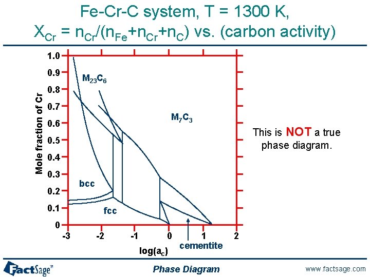
It is evident from Figure 6 (Fe-Cr-C phase diagram) that typical martensitic steels should exhibit ferrite and M 23 C 6 in equilibrium at for example, 600°C. In practice, this carbide is only found after relatively long ageing. because it is preceded by Intermediate phases in the sequence cementite, M 2 X and M 7 C 3 , leading finally to M 23 ...

Figure 6.1 from MTDATA - thermodynamic and phase equilibrium ...
1. Locate composition and temperature in diagram 2. In two phase region draw the tie line or isotherm 3. Fraction of a phase is determined by taking the length of the tie line to the phase boundary for the other phase, and dividing by the total length of tie line The lever rule is a mechanical analogy to the mass balance calculation.
Sigma-phase in Fe-Cr and Fe-V alloy systems and its physical ...
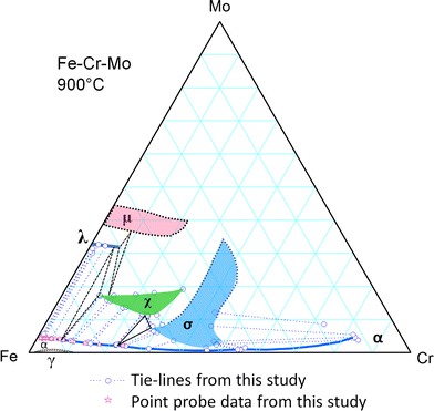
Determination of the Fe-Cr-Ni and Fe-Cr-Mo Phase Diagrams at Intermediate Temperatures using a Novel Dual-Anneal Diffusion-Multiple Approach Cao, Siwei Phase diagrams at intermediate temperatures are critical both for alloy design and for improving the reliability of thermodynamic databases.
.png)
Fe-Cr-B (1000 K) | Japan Atomic Energy Agency
Transmission electron microscopy and the corresponding selected-area electron diffraction patterns of Fe-(10;20;30;40;47) wt. pct. Cr alloys heat treated isothermally from 500°C up to 1500°C at 100°C was employed to construct the equilibrium Fe-rich portion of the Fe-Cr phase diagram. It has been found to be quite different from the generally accepted one. Two regions of phase separation ...
Experimental Investigation of the Phase Relationship of the ...
SpMCBN - Spencer Group M-C-N-B-Si Alloy Phase Diagrams (837) Click on a system to display the phase diagram.

File:Phase diagram of Fe-Cr.svg - Wikimedia Commons
Aug 04, 2021 · Interestingly, on the R-Fe (R = rare earth) binary phase diagram 26 (see Supplementary Fig. 1), Fe forms a eutectic system with R 2 Fe 17 —a typical negative thermal expansion (NTE ...

Figure 13 | Determination of the Fe-Cr-Mo Phase Diagram at ...
For example, the first figure below is the T(C) versus Wt.% C phase diagram of the Fe-Cr-C system at 2.8 Wt.% Cr calculated under normal equilibrium conditions (orthoequilibrium). Data are taken from the SGTE 2011 databases. The second figure is the paraequilibrium diagram for the same system when C is the only diffusing component.
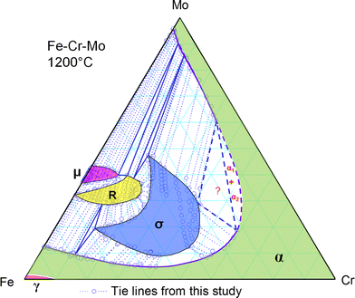
Determination of the Fe-Cr-Mo Phase Diagram at Intermediate ...
Cr-Fe-Ti Ternary Phase Diagram Evaluation. Phase diagrams, crystallographic and thermodynamic data. Volodymyr Ivanchenko and Tetyana Pryadko and MSIT® Abstract. This report for the ternary system Cr-Fe-Ti discusses binary systems, solid phases, invariant equilibria, liquidus, solidus and solvus surfaces, isothermal sections, temperature ...
Metals | Free Full-Text | Study on σ Phase in Fe–Al–Cr Alloys ...
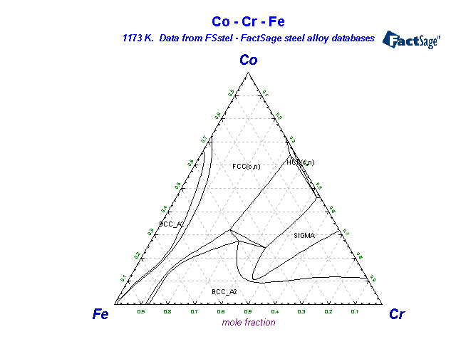
No phase diagram was found for the Fe-Cr-N pp. 4101-07. 3. High-Nitrogen Steel-88, Conf. Proc., Lille, France, May 18-20, 1988, system at 1173 K for high nitrogen contents as those attained J. Foct and A. Hendry, eds. The Institute of Metals, London, 1989. in this research work. Hence, considering the reported iso- 4. ...
![The binary Fe-Cr phase diagram [17]. | Download Scientific ...](https://www.researchgate.net/profile/Bandar-Al-Mangour/publication/298083929/figure/fig2/AS:372568361062401@1465838627342/The-binary-Fe-Cr-phase-diagram-17.png)
The binary Fe-Cr phase diagram [17]. | Download Scientific ...
金 属 / metal. セラミックス / ceramics. 水 溶 液 / aqua(予定). エリンガム図 / ellingham *注意* 計算熱力学はいわば”物性推算法”の一つであり、用いる熱力学データベースも、もっとも良さそうな”推算値”で構成されています。
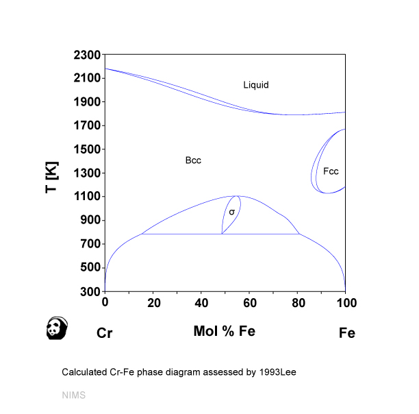
Cr-Fe (NIMS)
3) Isothermal phase diagram of Fe-Cr-O system at 1 600°C was established. The relationshp between the chromium content of Fe-Cr melt and the oxide phase equilibrated was determined. below 1% Cr-cubic chromite, 1-7%Cr-c/a=1-0.95 above 7% Cr-Cr 2 O 3
General Phase Diagram Sections Arthur D Pelton Centre
The re-calculated phase diagram of the Fe-Cr system based on the present study is shown in Fig. 1. As expected, the FCC γ-loop is observed on the Fe-rich side. The BCC phase has a large miscibility gap between Fe-rich (BCC) and Cr-rich (BCC') alloy compounds. σ phase is stable at elevated temperatures. Download : Download high-res image (105KB)
Determination of the Fe-Cr-Mo Phase Diagram at Intermediate ...
Phase diagram of Fe--Cr--Co permanent magnet system (Conference) | OSTI.GOV Phase diagram of Fe--Cr--Co permanent magnet system Abstract The miscibility gap of the ..cap alpha.. phase in Fe-Cr-Co permanent magnet alloys is constructed using mechanical hardness and Curie temperature measurements.
Ternary Phase Diagrams
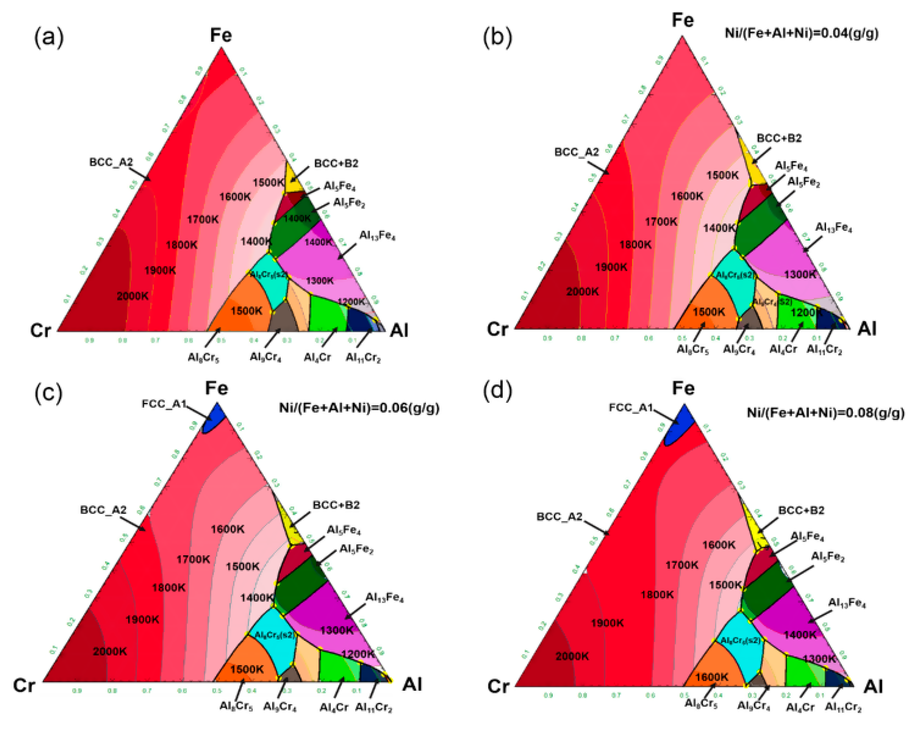
The phase diagrams and elastic properties of the Fe-Cr-Al alloys in full-temperature and all-compositional ranges are calculated. By combining first-principles calculations and cluster variation method, binary and ternary phase diagrams are obtained.
Ternary phase diagram overview
192 / Phase Diagrams—Understanding the Basics. A hypothetical ternary phase space diagram made up of metals . A, B, and . C. is shown in Fig. 10.2. This diagram contains two binary eutectics on the two visible faces of the diagram, and a third binary eutectic between ele-ments . B. and . C. hidden on the back of the plot. Because it is ...
Composition equivalents of stainless steels understood via ...
Cr-Fe-Ni (Chromium-Iron-Nickel) Cr-Fe-Ni (Chromium-Iron-Nickel) Raghavan, V. 2008-12-05 00:00:00 JPEDAV (2009) 30:94-95 Section II: Phase Diagram Evaluations DOI: 10.1007/s11669-008-9449-y 1547-7037 ASM International V. Raghavan The detailed review of the early results of the phase (a¢) phases. The Cr-Ni phase diagram [Massalski2] has a equilibria of this system by [1988Ray] presented ...

Color online) The Fe-Cr phase diagram. The lines correspond ...
The potential reproduces, for example, the lattice parameter(s), formation energies and elastic properties of the principal Fe and Cr carbides (Fe3C, Fe5C2, Fe7C3, Cr3C2, Cr7C3, Cr23C6), the Fe–Cr mixing energy curve, formation energies of simple C point defects in Fe and Cr, and the martensite lattice anisotropy, with fair to excellent ...

Ferritic stainless steel - Wikiwand
1273K-C-Cr-Fe FSstel: 1273K-C-Fe-Mn FSstel: Ag-Al FScopp: Ag-Al FTlite: Ag-Al SGnobl: Ag-Al SGTE 2014: Ag-Al SGTE 2017: Ag-Al SGTE 2020: Ag-Al-Au_500C SGnobl: Ag-Al-Bi_870C SGnobl: Ag-Al-In_650C SGnobl: Ag-Al-Mg_liquidus SGnobl: Ag-Al-Pb_870C SGnobl: Ag-Al-Si_500C SGnobl: Ag-Al-Si_liquidus SGnobl. Ag-Al-Sn_25C SGnobl: Ag-Al-Sn_liquidus SGnobl ...
1. Introduction High carbon alloys from Fe-Cr system are well ...
the ternary phase diagram with respect to the aus-tenite stabilized region in the low Cr composition has not beenentirely identified evenin the recent st.udy. Thepurpose of this study is to investigate the eq,ui-librium phasediagram of Fe-Cr-Mnsystem at 923 K (650'C), in particular, to examine the extent of a single phase reg_ion in the low Cr ...
What are stainless steels? - ppt download
Phase Diagram 1. Chapter-5 PHASE AND PHASE EQUILIBRIUM Prepared By: PALLAV RADIA Asst prof. AITS, RAJKOT. 2. Introduction: One of the most important objective of engineering metallurgy is to determine properties of material. The properties of material is a function of the microstructure which depend on the overall composition and variable such as pressure and temperature. Hence to determine ...
1: Fe-Cr phase diagram (a) [18]; Fe-Cr-0.1C phase diagram (b ...

Ni Laboratory
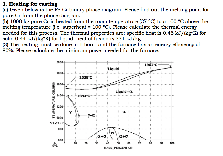
Solved (a) Given below is the Fe-Cr binary phase diagram ...

Figure 41 from A Thermodynamic Analysis of the System Fe-Cr ...

File:Fe-Cr-Ni-solidus-phase-diagram.svg - Wikimedia Commons
Review: precipitation in austenitic stainless steels
Short-term Mechanical Properties of Fe-Cr-Al-Si Alloys | KnE ...
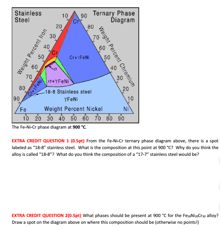
Solved From the Fe-Ni-Cr ternary phase diagram above, there ...
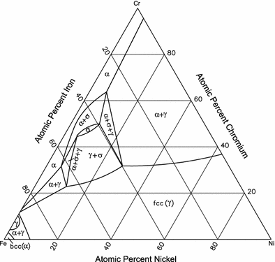
Cr-Fe-Ni (Chromium-Iron-Nickel) | SpringerLink

File:Fe-Cr Phase Diagram.gif - Wikiversity
Critical Reviews in Solid State and Materials Sciences Phase ...

The structurization and properties of Fe–Cr–C alloys with a ...
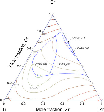
Thermodynamic description of hydrogen storage materials Cr–Ti ...
FSstel - FactSage Steel Alloy Phase Diagrams

A thermodynamic evaluation of the Fe–Cr–C system - ScienceDirect

Phase diagram in Fe±Cr±Ni system and composition of samples ...
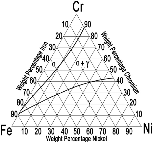
Ternary Diagram for Wrought Austenitic Stainless Steels

Austenitic Steels :: Total Materia Article

File:Diagramme phase Fe Cr Ni.svg - Wikimedia Commons
0 Response to "40 fe cr phase diagram"
Post a Comment