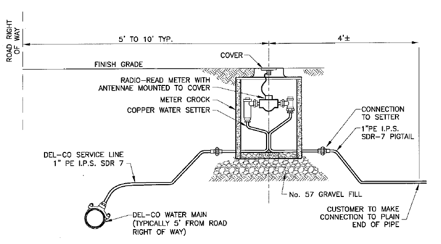
36 water meter installation diagram
terminals in the flow meter. See Figure 7. A wiring diagram decal is located adjacent to the field wiring terminals within the FUSION enclosure. If the flow meter is only to be utilized as a flow rate indicator or totalizer, no further wiring will be required. Skip to the Flow Meter Configuration section of this manual (see page 19).
WATER METER & BACKFLOW PREVENTION PAGE 3 SECTION 2 - DEFINITIONS MAY 2017 2.0 DEFINITIONS Approval Refers to the approval of the Engineer. The Engineer's decision will be final and binding in matters of design, installation,
Cathodic Protection Wiring Diagram W-0850 3" & 4" Compound Meter Installation W-0860 3" Turbo Meter Installation W-0870 Typical Plan Layout Sewer Systems W-1000 Typical Pipe Bedding Vitrified Clay Pipe Extra Strength W-1010 Concrete Arch W-1020 Classes "BB", "B", "C" & "D" Beddings W-1030 Concrete Encasement W-1040
Water meter installation diagram
8 Standard Manifold Meter Setting, 5/8", 3/4", 2017-009-08 . and 1" Disc Meters . 9 Standard Meter Setting, 1 1/2 " and 2" MVR Meters 2017-009-09 . 10 Standard for 1 1/2" and 2" Meter Pit Detail 2017-009-10 . 11 Standard Large Meter Installation 2017-009-11 . 12 Standard Fire and Domestic Manifold Setting (Conventional
The primary purpose of a water meter is to measure the flow of water flowing into the home. Therefore, if you have a well, you may want to install a water meter yourself to measure how much water you use from the well. Step One - Ready Indoor Plumbing. Before you install your water meter, all of the interior plumbing must be ready to accept water.
34 WATer MeTerS—SeleCTIon, InSTAllATIon, TeSTIng, And MAInTenAnCe All compound meters lose a certain degree of accuracy operating within the changeover flow range by varying amounts. It is important to size any compound meter installation to minimize the total flow each installation experiences in the changeover flow range.
Water meter installation diagram.
1. The meter and main switch shall be accessible for reading and maintenance without requiring passage through restricted areas, gates, or fences. 2. All meter and main switches shall be located three feet minimum to six feet maximum on the front corner of a residence, nearest to the point of available service, as determined by CRA-ES on
(7) The water meter should be installed by a qualified, experienced professional. Upon installation, each water meter must be inspected by District staff. If you have any questions regarding installation of water meters or would lik e to schedule an inspection, please do not hesitate to call (831) 658-5642. revised 04/13/2000
This helpful instructional video will help you learn how to correctly install a water meter. For more information, http://austintexas.gov/department/taps
Turbine Flow Meter Manual 04/16 - 0721-6 / 13518 Page 7 SECTION 2.0: UNPACKING Turbine flow meters are generally shipped in one package unless optional hardware or equipment is ordered. This package may contain up to two complete meters along with the optional installation kits. Any display equipment ordered with the meters, will be packed ...
An installation diagram is provided on the following page illustrating the proper installation requirements. Permit and Meter Fees 12. A 3/4" water meter typically used for outside hose bibbs is $148.00 (incl. tax). A 1"water meter typically used for outside lawn irrigation systems is $227 .00 (incl. tax) 14.
WATER METER SPECIFICATION 1. DOMESTIC WATER METER SPECIFICATIONS (15MM, 20MM AND 25MM SIZES) 1.1 GENERAL LAYOUT The complete water meter is to consist of (5) components: Above ground extruded water meter box and extended lid with slider. A water meter (Plastic bodied 15mm, 20mm and 25mm) class C volumetric rotary
d-23 new copper 1-inch water service standard meter vault d-24 new copper 1.5 n. & 2 in. water service standard meter vault d-25 3 inch, 4 inch, 6 inch, 8 inch & 12 inch meter vaults d-26 12 inch meter vault with check valve d-27 typical meter installation for 1 inch water service with lawn hydrant and backflow preventor
water meter must be installed in such a manner to confirm that the water meter complies with AS4747 and the manufacturer's recommendations. The licensee must ensure a new or replacement priority meter installation is certified by a certified meter installation validator.
Water meters have to be installed where water first enters the customer's property. Please refer to the general diagram below. Water is supplied to your home through a series of pipes. As shown in the diagram, water is supplied to all the homes on your street through a "water main" pipe. The "water main" pipe preferrably located in the
Pipe Lengths Rule of Thumb: You must have at least 10 pipe diameters in pipe length before the water meter and at least 5 pipe diameters in pipe length after the water meter. For example if you have 1.5 inch pipe and water meter you would want 15 inches of straight pipe before your water meter and 7.5 inches of straight pipe after your water meter.
and private water services, type and size of meter to use, who supplies and installs the meter, meter installation details, pipe and fitting installation, backflow prevention assemblies, fire hydrant permits, and
Check the water meter for the proper direction of flow. The meter will have some kind of flow direction indicator located on the top or sides of the meter. Then install the new meter and rubber gaskets. For proper installation, never use a wrench to start the thread connections. Always start the meter connections by hand to make sure that the ...
with Water Supply (Water Quality) Regulations 2000 and Water Supply (Water Fittings) Regulations 1999. Internal manifold must be installed by the Developer as per the example diagram below. Anglian Water will supply and install the meters. The manifold system must be Regulation 4 compliant and installed a maximum of one metre
W-31 Typical 1 ½ "- 2" Water Meter Box Installation W-32 Typical 4" Water Meter Vault W-33 Typical 6" thru 10" Water Meter Vault W-34 Fire, Domestic & Irrigation Options Schematic W-35 Irrigation Tap on New and Existing Services W-35T Termination of Irrigation Meter W-36 Reduced Pressure Backflow Preventer ...
GETTING TO KNOW YOUR METER ASSEMBLY Diagram of Typical Meter Installation. Meter Assembly Component 1. Isolation Valve (attached to waterline from street) 2. Water Meter Frost Plate (sacrificial black steel, under meter, will break if frozen) 3. Water Meter Base 4. Water Meter Register Head 5. Dual Check Backflow Preventer (DuC) 6.
See Appendix 1 - Diagram 2 (page 8) which shows an illustration of a typical single meter installation of in-line meter internal (not on manifold). Diagram 3 (page 9) shows, a meter carrier for a single and/or multiple internal meter installation (which can also be used on a multiple manifold).
Carlon Meter Product Installation Instructions. Carlon Meter - Water Meters - Industrial, Commercial, and Municipal water meters and electronic control. Carlon Meter manufactures and distributes water meters and electronic controls for the industrial and commercial markets, as well as municipal type water meters ...
You need this material: *- A water meter (of course!) in mi case a 3/4 new generation polymer home water meter. *- 1st step water filter (this can be removed) but i considered usefull. *- 2 3/4 galvanized union nut. (it can be copper but it´s more expensive) *- 2 3/4 copper elbows. *- 1 3/4 copper elbow with rope. *- 4 3/4 copper weldable coupling. If you removed water filter only use 2. *- 3 ...
Why the T-10 ®?. Long trusted by thousands of utilities across North America, Neptune T-10 ® water meters are time-proven for accuracy and dependability even at low flow rates and provide a wide effective flow range for maximum revenue. The T-10 water meter is manufactured right here in America in our own foundry using proprietary technology.
Installation of water meters makes the gallons of water used per unit drop. It can also have additional benefits in energy conservation without adding the extra cost of installing electric submeters. This is simply because being billed for the gallons you use typically results in shorter showers and more efficient dish and laundry washing.
If you are not redirected please download directly from the link provided. Download
6. To ensure proper meter installation, each meter socket and its disconnect switch shall be clearly and uniquely identified and marked/placarded (e.g., "SOLAR PRODUCTION") prior to the start of any service work. If there is more than one
Water Meter Diagram. This photo includes instructions to help you identify, read, and record usage information from your water meter. The Philadelphia Water Department (PWD) is upgrading customers' existing water meters as part of an Advanced Metering Infrastructure (AMI) project starting January 2021.

0 Response to "36 water meter installation diagram"
Post a Comment