34 iron carbon phase diagram explained
Phase diagram is a graphical representation of the physical states of a substance under different conditions of temperature and pressure. A typical phase diagram has pressure on the y-axis and temperature on the x-axis. As we cross the lines or curves on the phase diagram, a phase change occurs. In addition, two states of the substance coexist ...
Time-Temperature-Transformation Diagram. It is obvious that the equilibrium phase digram (Fig. 1) does not contain any information about phases such as bainite, martensite etc. This is because it represents equilibrium whereas the variety of transformation products have a range of deviations from the equilibrium state.
Time Temperature Transformation (TTT) Diagram Below A 1 , austenite is unstable, i.e., it can transform into pearlite, bainite or martensite. The phases finally formed during cooling depend upon
Iron carbon phase diagram explained
Bearings in internal combustion engines, Engine parameters determining bearing loading, Lubrication regimes, Hydrodynamic journal bearing, Hydrodynamic lubrication theory, Geometrical parameters of engine bearings, Mechanisms of wear, Requirements to engine bearing materials, Engine bearing fatigue test, Engine bearing materials, Copper based bearing materials, Manufacturing bi-metal strips ...
T (Time) T(Temperature) T(Transformation) diagram is a plot of temperature versus the logarithm of time for a steel alloy of definite composition.
13.2 Phase Diagrams: Binary Systems. As explained in Sec. 8.2, a phase diagram is a kind of two-dimensional map that shows which phase or phases are stable under a given set of conditions. This section discusses some common kinds of binary systems, and Sec. 13.3 will describe some interesting ternary systems.
Iron carbon phase diagram explained.
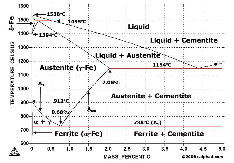
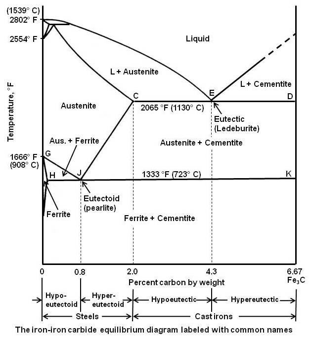
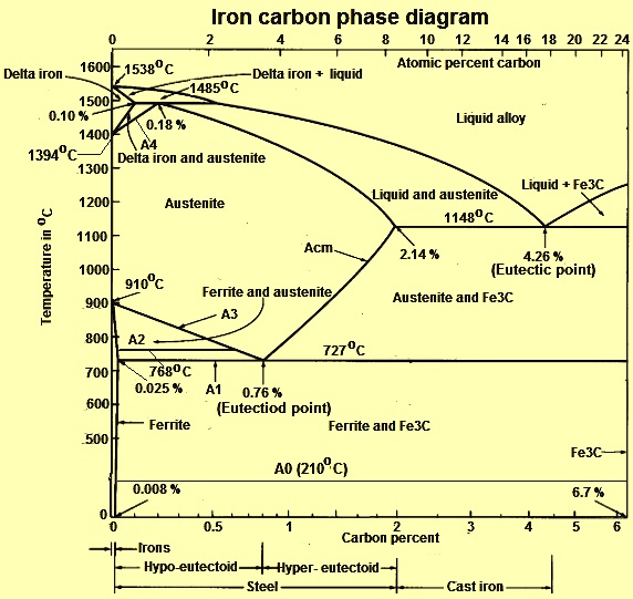
Firstly, there is the A 1, temperature at which the eutectoid reaction occurs (P-S-K), which is 723°C in the binary diagram.; Secondly, there is the A 3, temperature when α-iron transforms to γ-iron.For pure iron this occurs at 910°C, but the transformation temperature is progressively lowered along the line GS by the addition of carbon.
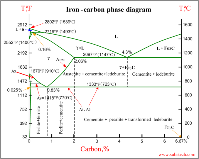
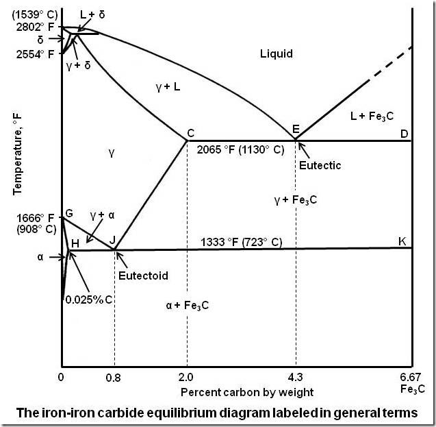
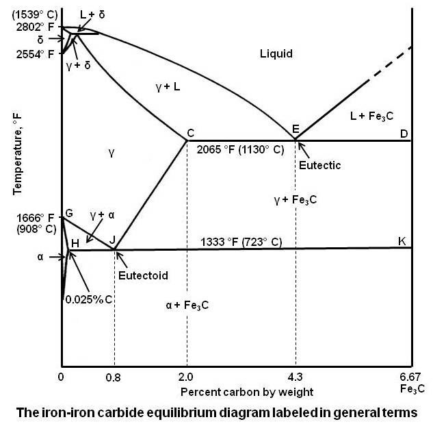
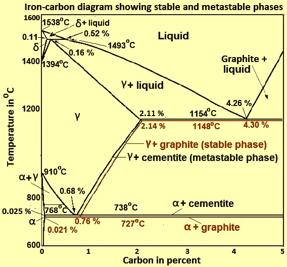
The Iron-Iron Carbide Diagram The diagram shows three horizontal lines which indicate isothermal reactions (on cooling / heating): First horizontal line is at 1490°C, where peritectic reaction takes place: Liquid + δ ↔ austenite Second horizontal line is at 1130°C, where eutectic reaction takes place: liquid ↔ austenite + cementite Third ...
Its chemical formula is Fe 3 C. It contains 6.67 percent carbon by weight. It is a hard and brittle interstitial compound of low tensile strength (approximately 5000 psi) but high compressive strength. Its crystal structure is orthorhombic. It is the hardest structure that appears on the iron-iron carbide diagram.
Phase Diagram Evaluations: Section II The C-Fe (Carbon-Iron) System by Ho Okamoto ASM International Equilibrium Diagram The number of experimental and theoretical publications on the
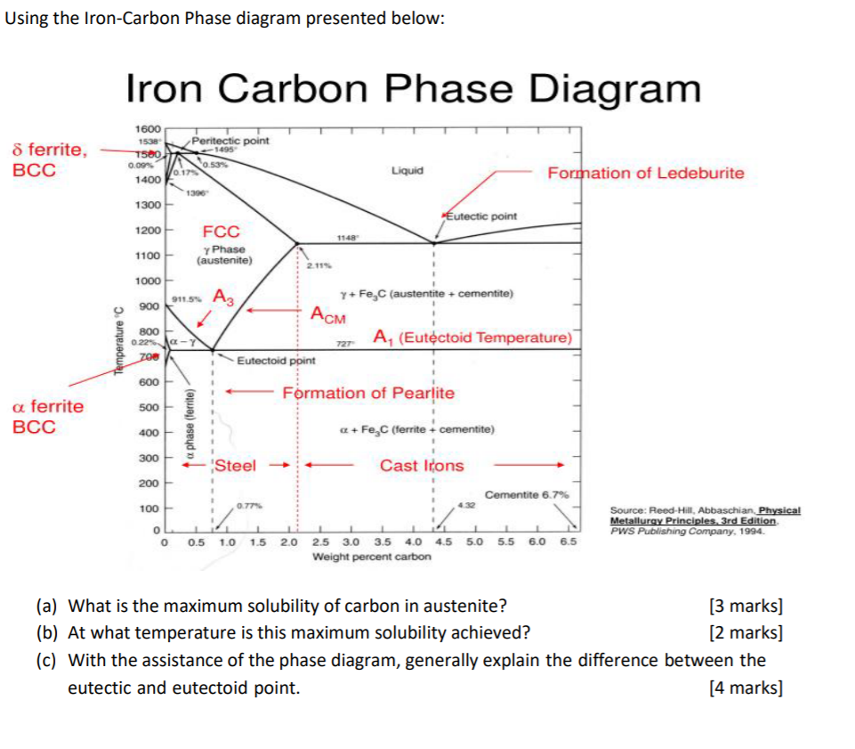
Upper critical temperature (point) A 3 is the temperature, below which ferrite starts to form as a result of ejection from austenite in the hypoeutectoid alloys. Upper critical temperature (point) A CM is the temperature, below which cementite starts to form as a result of
Carbon Steels and the Iron-Carbon Phase Diagram. Steels are alloys having elements of iron (Fe) and carbon (C). C gets dissolved in Fe during the production of steels. Pure Fe melts at a temperature of 1540 deg C, and at this temperature, C readily dissolves into the liquid iron, generating a liquid solution.
Introduction. In principle, steels are binary systems consisting of the host element iron and the alloying element carbon with a maximum content of 2 % (above 2% carbon, the iron-carbon alloy is called cast iron!).The carbon provides the necessary strength and hardness because iron alone would be too soft as a construction material.
The iron-carbon diagramLearning objectives:- You name and describe the different phases of pure iron during the cooling process.- You distinguish between met...
Cementite is a chemical compound of carbon with iron and is known as iron carbide (Fe3C). Cast iron having 6.67% carbon is possessing complete structure of cementite. Free cementite is found in all steel containing more than 0.83% carbon. It increases with increase in carbon % as reflected in Fe-C Equilibrium diagram. It is extremely hard.
Principles of Physical Metallurgy by Prof. R.N. Ghosh,Department of Metallurgy and Material Science,IIT Kharagpur.For more details on NPTEL visit http://npt...
1. Ferrite: It is a solid solution of upto 0.025% carbon in the solvent a-iron. This phase is indicated in the diagram by GSP. ϒ phase is converted to ferrite due to slow cooling of the solid alloys. Ferrite generally contains no carbon but many other elements such as Mn, Si, Cr in the solid solution. Ferrite is soft, weak and ductile.
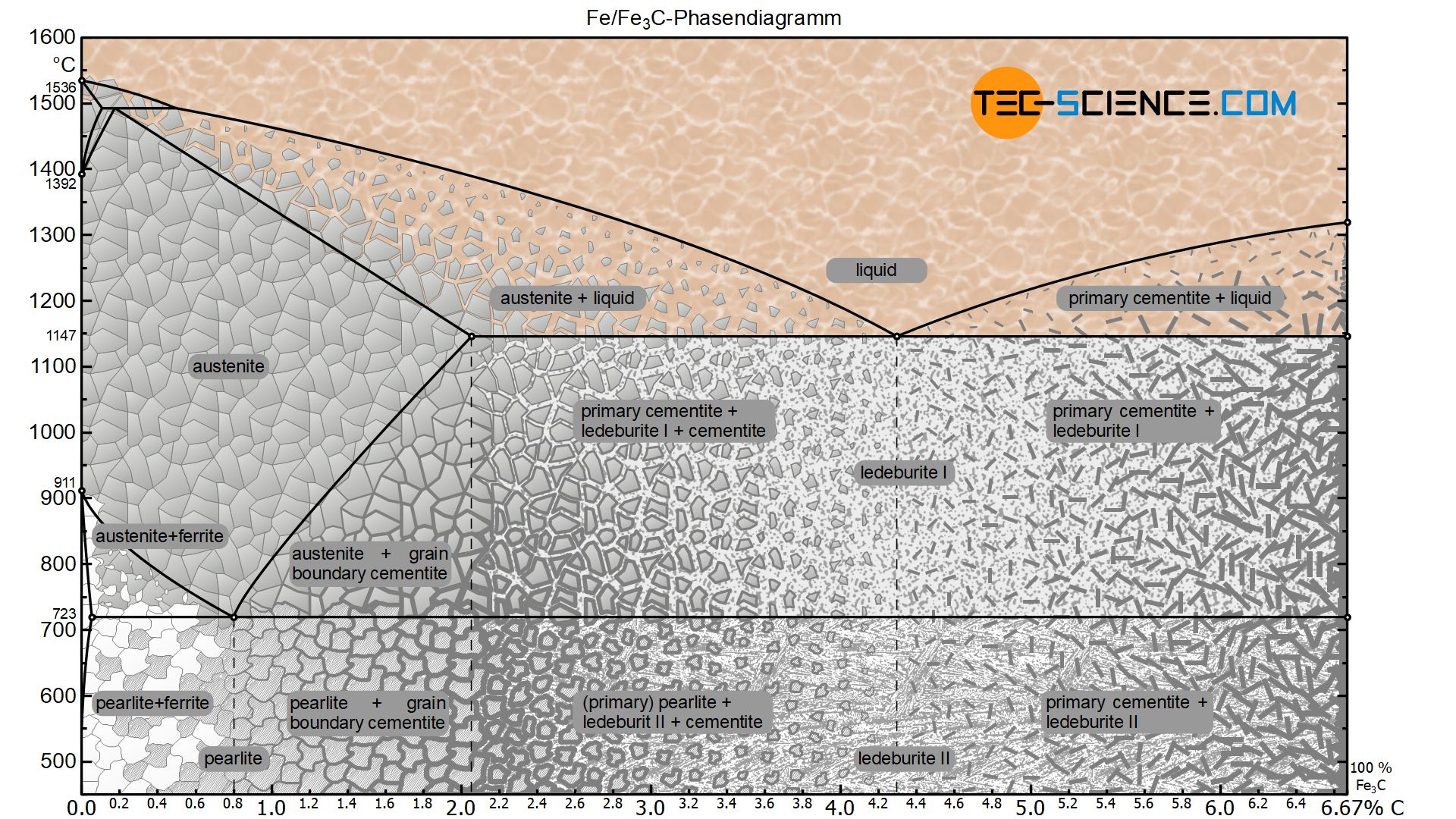
Iron-carbon phase diagram. Phase diagram for the binary system iron-carbon (Fe-C). The phase composition depending on the temperature and the carbon content can be read off this dual diagram in which the stable system iron-graphite (dotted lines) and the meta-stable system iron- carbide (solid lines) are shown together, (Figure 1). The ...
Iron-carbon phase diagram [substech]
Cementite is a chemical compound of carbon with iron and is known as iron carbide (Fe3C). Cast iron having 6.67% carbon is possessing complete structure of cementite. Free cementite is found in all steel containing more than 0.83% carbon. It increases with increase in carbon % as reflected in Fe-C Equilibrium diagram. It is extremely hard.
![The iron-carbon phase diagram [46]. | Download Scientific Diagram](https://www.researchgate.net/profile/Muna-Abbass/publication/293333803/figure/fig2/AS:669013386469398@1536516629671/Figure-2-11-The-iron-carbon-phase-diagram-46.png)
The iron-carbon phase diagram [46]. | download scientific diagram
Answer: Iron loses its magnetic nature at 1043K and early investigators found that this loss is due to phase transformation and named the paramagnetic iron( above 1043K) as beta iron.Later it was found that the loss in magnetic nature is not because of phase transformation and they removed the be...
Bisakah anda menjelaskan diagram besi karbida besi (diagram ...
Conventionally, the complete Fe-C diagram should extend from 100% Fe to 100% carbon, but it is normally studied up to around 6.67% carbon as is also illustrated in Fig. 1.22, because iron alloys of practical industrial importance contain not more than 5% carbon. Thus, this diagram is only just a part of the complete Fe-C equilibrium diagram.

The iron carbon phase diagram
A study of the microstructure of all steels usually starts with the metastable iron-carbon (Fe-C) binary phase diagram (Figure 1). It provides an invaluable foundation on which to build knowledge of both carbon steels and alloy steels, as well as a number of various heat treatments they are usually subjected to (hardening, annealing, etc).

File:iron carbon phase diagram.svg - wikimedia commons
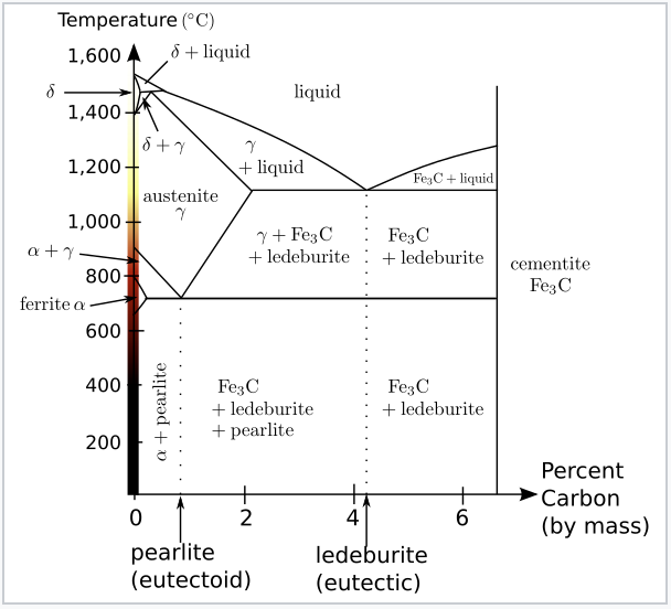
Iron Carbon phase diagram. On this diagram, the carbon percentage is shown on the x-axis and temperature on the y-axis. This figure shows the Iron Carbon Equilibrium Diagram. In this diagram, the lines indicate the boundaries where the alloy changes its phase. The different phases or mixture of phases occur in different areas enclosed by these ...
File:iron carbon phase diagram.svg - wikimedia commons
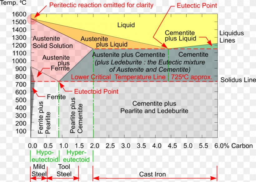
The important boundaries (the lines) separating phases have some universally used abbreviations:. A 1: The upper limit of the ferrite / cementite phase field (horizontal line going through the eutectoid point).; A 2: The temperature where iron looses its magnetism (so-called Curie temperature).Note that for pure iron this is still in the a-phase.; A 3: The boundary between the g austenite and ...
![Iron-Carbon equilibrium diagram [62] | Download Scientific ...](https://www.researchgate.net/profile/Ashwin-Polishetty/publication/268747490/figure/fig11/AS:670010443833358@1536754346351/Iron-Carbon-equilibrium-diagram-62.png)
Iron-carbon equilibrium diagram [62] | download scientific ...
Definition of structures: Austenite is an interstitial solid solution of Carbon dissolved in (F.C.C.) iron. Maximum solubility is 2.0 % C at 1130°C. High formability, most of heat treatments begin with this single phase. It is normally not stable at room temperature. But, under certain conditions it is possible to obtain austenite at room temperature.

Iron-carbon equilibrium phase diagram ... | materials ...
Dr. Dmitri Kopeliovich Iron-carbon phase diagram describes the iron-carbon system of alloys containing up to 6.67% of carbon, discloses the phases compositions and their transformations occurring with the alloys during their cooling or heating.. Carbon content 6.67% corresponds to the fixed composition of the iron carbide Fe 3 C. . The diagram is presented in the picture:

The iron-carbon alloys and fe-c phase diagram - mechanicalbase
Fig 1 Iron carbon phase diagram. C is an interstitial impurity in Fe. It forms a solid solution with alpha, gamma and delta phases of iron. Maximum solubility of C in alpha iron is 0.025 % at 727 deg C. Body centred cubic (BCC) iron has relatively small interstitial positions. Maximum solubility of C in the face centred cubic (FCC) gamma iron ...
Iron-iron carbide phase diagram example
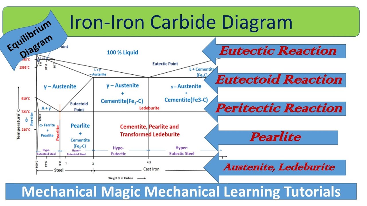
Iron-Carbon Phase Diagram with Detailed Explanation: If the percentage of the carbon is in the range of 0 to 2.11 % then it is called Steel and if the percentage of carbon is in the range of 2.11 to 6.67% then it is called Cast iron. As the carbon content increases, it produces more Iron-Carbide volume and that phase will exhibit high hardness.
Phase diagram iron carbon | metallurgy for dummies
Iron-Carbon Phase Diagram. The iron-carbon phase diagram is widely used to understand the different phases of steel and cast iron. Both steel and cast iron are a mix of iron and carbon. Also, both alloys contain a small amount of trace elements. The graph is quite complex but since we are limiting our exploration to Fe3C, we will only be ...
What is the use of an iron carbide phase diagram? - quora
Practical maintenance » blog archive » the iron-iron carbide ...

Week13 iron carbon phase diagram pdf | pdf | cast iron | steel
How to draw iron carbon diagram | iron carbon diagram explained| iron carbon diagram

Difference between steel and cast iron - engineering

The iron-carbon equilibrium diagram :: total materia article

Iron-carbon phase diagram |
Practical maintenance » blog archive » the iron-iron carbide ...

Iron carbon phase diagram
Sketch and explain the iron carbon equilibrium diagram ...
Iron–iron carbide (fe–fe3c) phase diagram

Welding , hardfacing , cladding and cutting of metals ...

Iron carbon phase diagram - google search | metal working ...
7.4: iron and steel - chemistry libretexts
The iron-carbon phase diagram – ispatguru
Solved using the iron-carbon phase diagram presented below ...

Please answer the following question regarding the iron-iron ...
Iron-carbon phase diagram steel cementite, png, 1000x714px ...

Teach yourself phase diagrams
Determination of microstructure and phase fractions in steels ...

Iron-carbon phase diagram (a review) see callister chapter 9 ...
The iron-carbon phase diagram – ispatguru
0 Response to "34 iron carbon phase diagram explained"
Post a Comment