38 curtis controller wiring diagram
Fig. 4 Basic wiring diagram, Curtis 1204M/05M/09M/21M with active main contactor. 2 — INSTALLATION & WIRING: Standard Wiring Diagrams CONTROLLER WIRING: BASIC CONFIGURATIONS Two basic wiring diagrams are shown; they are identical except for the wiring at terminal J5. In the configuration in Figure 4, the main contactor driver is active. Curtis 1268 controllers are separately excited motor speed controllers designed for ... This wiring is also shown in the standard wiring diagrams, Figs.68 pages
Curtis Controller Wiring Diagram - curtis 1205 controller wiring diagram, curtis 1206 controller wiring diagram, curtis 1225 controller wiring diagram, Every electrical arrangement consists of various unique parts. Each component ought to be set and connected with different parts in particular way. If not, the structure won't function as it should be.
Curtis controller wiring diagram
Curtis Speed Controller Wiring Diagram Curtis 1234 1236 or 1238 Ac Motor Speed Controller is one of the pictures that are related to the picture before in the collection gallery, uploaded by autocardesign.org.You can also look for some pictures that related to Wiring Diagram by scroll down to collection on below this picture. If you want to find the other picture or article about Curtis Speed ... Wiring diagram for 36 48v stand up dc series motor controller assemblage 36v 500a curtis programmable sd electrical upgrade 1204 020 160a help sepex electric and ipm system 32kw brushless pmc 1266a 5201 Wiring Diagram For 36 48v Stand Up Models With Curtis Controller Dc Series Motor Controller Assemblage Curtis 1204m 5203 36v 48v 275a 36v… Read More » curtis controller wiring diagram - You'll need a comprehensive, professional, and easy to understand Wiring Diagram. With this sort of an illustrative manual, you'll be able to troubleshoot, avoid, and complete your tasks with ease. Not merely will it help you achieve your required final results quicker, but also make the complete process ...
Curtis controller wiring diagram. Curtis Controller Wiring Diagram - curtis 1205 controller wiring diagram, curtis 1206 controller wiring diagram, curtis 1225 controller wiring diagram, Every electrical arrangement is made up of various distinct parts. Each part should be set and linked to different parts in particular manner. If not, the arrangement won't work as it should be. Fig. 3 Basic wiring diagram, Curtis 1204M/05M motor controller. 2 — INSTALLATION & WIRING: Standard Wiring Diagram CONTROLLER WIRING: BASIC CONFIGURATION A basic wiring diagram for the 1204M/05M controller is shown in Figure 3. The throttle shown in the diagram is a 2-wire potentiometer; voltage throttles can also be used. Curtis M, M, M, and M series motor controllers are the . 4 Basic wiring diagram, Curtis M/05M/09M/21M with active main contactor. Before starting these tests, refer to the appropriate wiring diagrams and make sure your controller is hooked up properly. Curtis Controller Wiring Diagram. Variety of curtis controller wiring diagram. A wiring diagram is a streamlined standard photographic representation of an electrical circuit. It reveals the parts of the circuit as simplified shapes, and also the power and signal connections between the tools. A wiring diagram generally offers details concerning the loved one setting…
Push-on connectors for control wiring Familiarity with your Curtis PMC controller will help you to install and operate it properly. We encourage you to read this manual carefully. If you have questions, please contact the Curtis office nearest you. 2 — INSTALLATION AND WIRING pg. 3 Return to TOC Curtis 1232E/34E/36E/38E & 1232SE/34SE/36SE/38SE Manual, os 31 - May 2017 2 — INSTALLATION AND WIRING MOUNTING THE CONTROLLER The outline and mounting hole dimensions for the 1232E/SE controller are shown in Figure 2a, for the Curtis Controller Wiring Diagram 48 Volt Golf Cart | Wiring Diagram - Curtis Controller Wiring Diagram. Wiring Diagram will come with several easy to adhere to Wiring Diagram Guidelines. It's supposed to help all the typical consumer in creating a correct program. These directions will probably be easy to comprehend and implement. Wiring diagram for 36 48v stand up programmable dc series motor controller curtis sd 1268 5403 assembly 1204 020 160a help michael golub electric truck electrical upgrade ipm system 32kw brushless and golf cart circuit diy car. Programmable Dc Series Motor Controller Model P125m 4601 24v 400a Economic Replacement Of Curtis Old Models 1205 101 ...
Circuit Diagram for Wesley. International Pack Mule Including. Options. 36-48V Stand-Up. Curtis. Controller Part Number EV-E189-48. Released July 20, 2012. Curtis Controller Documents . Instructions. Fairplay Kinitek KCCA004 to Curtis 1266 Conversion Instructions. Curtis 1510(A) Installation Sheet for Club Car Precedent IQ. Curtis 1206-03/04 Installation Sheet for E-Z-GO TXT. Curtis 1206HB Installation Sheet for E-Z-GO TXT. Curtis 1206SX Installation Sheet for E-Z-GO DCS A-1 Block diagram, Curtis 1204/1205 controller .....A-1 FIG. B-1 Pulse width modulation ... Push-on connectors for control wiring Familiarity with your Curtis controller will help you to install and operate it properly. We encourage you to read this manual carefully. If you have Curtis 1234/36/38 Manual, OS11 3 16 FEBRUARY 2008 DRAFT 2 — INSTALLATION & WIRING 2 Fig. 2a Mounting dimensions, Curtis 1234 motor controller. Dimensions in millimeters (and inches)
APPLICATION Curtis PMC Model SepEx® controllers are programmable TYPICAL WIRING DIAGRAM. 1 2: Mounting dimensions, Curtis controller . 4 .. This wiring is also shown in the standard wiring diagrams, Figs. 3a and 3b.The Curtis PMC C electronic DC motor speed controller is designed for permanent magnet motor applications in mobility aids ...
Curtis Snow Plow Wiring Diagram - Curtis sno-pro 3000 Truck side wiring kit control harness power 2 plug 1UHT. Plow drivers are tasked with keeping the roads clear so drivers can get to where they need to be, safely. Meyer manufactures snow plows which you can mount on any truck.
Curtis and fsip websites don't have 3blade wiring diagrams anywhere. I need to make sure I'm running high voltage cables to the proper spots on f/r switch ...
wiring diagram. (series motor),. Curtis PMC 1207 controller. MULTI. MODE. EMERGENCY. REVERSE. A2. A1. REVERSE. CONTACTOR.
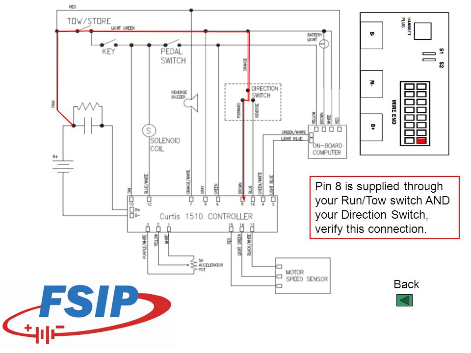
ELECTRONIC SPEED CONTROL Electric Vehicle 16 27 29 17 19 22 21 31 20 24 13 33 Splash Pan 1 - Includes Items 2 - 31 18 19. Service Parts Manual Page F-2 Electric Vehicle ELECTRONIC SPEED CONTROL Silver line on diode must be oriented as shown M-B-B+ ORN to MS4 (NC) BLK to Tab on Direction Selector RED to Solenoid LT. GRN to Key Switch 25 7 15 6 10 8
Curtis A and R controllers are motor speed controllers designed for use in a . To ensure full rated power, the controller should be fastened to a clean, . This wiring is also shown in the standard wiring diagrams, Figures 3a and 3b. .. This parameter is a conversion factor used to generate a vehicle speed.
CURTIS 1234 1236 or 1238 AC Motor Speed Controller. Architectural wiring diagrams discharge duty the approximate locations and interconnections of receptacles, lighting, and long-lasting electrical facilities in a building. Interconnecting wire routes may be shown approximately, where particular receptacles or fixtures must be upon a common circuit.
Curtis pmc pds controller wiring diagram manual 1999 curtis instruments, Results for 1510 5201 wiring diagram High Speed Direct Downloads 1510 5201 wiring diagram [Full Version] Curtis 1510 service notes | booklad.org curtis 1510 service notes book results. Follow: This manual contains important information for the setup
controllers, 1225/35 controllers, and 1227/37 controllers. The three individual installation and wiring sections are followed by common sections that cover throttle
11 Basic wiring diagram, Curtis 1204M-6302 motor controller—for pump applications. STATUS. LED. MOTOR. FIELD. A2. 5kΩ THROTTLE. PRECHARGE ...40 pages
curtis controller wiring diagram - You will want a comprehensive, skilled, and easy to understand Wiring Diagram. With such an illustrative manual, you'll be capable of troubleshoot, avoid, and full your assignments without difficulty.
48V Club Car Curtis Controller Wiring Diagram, Curtis Controller Capacitor, Ezgo Controller Wiring, Club Car Curtis Controller Wiring.The Curtis PMC C electronic DC motor speed controller is designed for permanent magnet motor applications in mobility aids, scrubbers, sweepers, AGVs, etc. It offers smooth, silent, cost-effective control of ...
input) must be connected to battery voltage as shown in the standard wiring diagram, Figure 3. The controller provides maximum braking torque as soon as the ...90 pages
4 Basic wiring diagram, Curtis M/05M/09M/21M with active main contactor.Find great deals on eBay for ezgo curtis controller. Shop with confidence. Wiring Diagrams for Club Car, EZ-GO and Yamaha Vehicle Controllers. Apr 12, · The Curtis M is amps and will work on a 93 EZGO Marathon at 36 or 48 volts.
Description: Curtis Sno-Pro 3000 Truck Side Wiring Kit Control Harness Power 2 with Curtis Snow Plow Wiring Diagram, image size 1147 X 674 px, and to view image details please click the image.. Here is a picture gallery about curtis snow plow wiring diagram complete with the description of the image, please find the image you need.
Fig. 4 Basic wiring diagram, Curtis 1204M/05M/09M/21M with active main contactor. 2 — INSTALLATION & WIRING: Standard Wiring Diagrams CONTROLLER WIRING: BASIC CONFIGURATIONS Two basic wiring diagrams are shown; they are identical except for the wiring at terminal J5. In the configuration in Figure4, the main contactor driver is active.
Curtis Controller 1206ac-5301 Wiring Diagram. Curtis controllers are separately excited motor speed controllers designed for use in a .. This wiring is also shown in the standard wiring diagrams, Figs. Controller Wiring Configuration, with active reverse input 8 .. 11 Basic wiring diagram, Curtis M motor controller—for pump applications.
curtis controller wiring diagram - You'll need a comprehensive, professional, and easy to understand Wiring Diagram. With this sort of an illustrative manual, you'll be able to troubleshoot, avoid, and complete your tasks with ease. Not merely will it help you achieve your required final results quicker, but also make the complete process ...
Wiring diagram for 36 48v stand up dc series motor controller assemblage 36v 500a curtis programmable sd electrical upgrade 1204 020 160a help sepex electric and ipm system 32kw brushless pmc 1266a 5201 Wiring Diagram For 36 48v Stand Up Models With Curtis Controller Dc Series Motor Controller Assemblage Curtis 1204m 5203 36v 48v 275a 36v… Read More »
Curtis Speed Controller Wiring Diagram Curtis 1234 1236 or 1238 Ac Motor Speed Controller is one of the pictures that are related to the picture before in the collection gallery, uploaded by autocardesign.org.You can also look for some pictures that related to Wiring Diagram by scroll down to collection on below this picture. If you want to find the other picture or article about Curtis Speed ...


0 Response to "38 curtis controller wiring diagram"
Post a Comment